Continue to Site

Welcome to EDAboard.com

Welcome to our site! EDAboard.com is an international Electronics Discussion Forum focused on EDA software, circuits, schematics, books, theory, papers, asic, pld, 8051, DSP, Network, RF, Analog Design, PCB, Service Manuals... and a whole lot more! To participate you need to register. Registration is free. Click here to register now.

How to add anti-windup to discrete PID?

Status
Not open for further replies.

powersys

Advanced Member level 1
Joined
Nov 29, 2005
Messages
439
Helped
3
Reputation
6
Reaction score
2
Trophy points
1,298
Activity points
4,981
Hi,

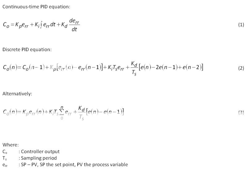
I have implemented the discrete PID controller, i.e. Eq.(2), in Texas C31 DSP. I wish to implement anti-windup as well. Kindly advise how to add anti-windup to the discrete PID controller.

By the way, do you think DSP implementation of Eq.(2) and Eq.(3) will give similar system performance?

Thanks.

discretePID123.png
 

I think (2), also known as the velocity algorithm is preferred for easy anti-windup implementation. Because co(n-1) represents the integrator, limiting it to the manipulated value range already does it. The real algorithm looks somewhat more simple than you have written it, using suitable intermediate results. So I think, it achieves a similar performance compared to (3).

For more general discrete controller implementation, it's a possible way to calculate minimum and maximum err values corresponding to the output limits backwards for the actual controller state and limit err as required.
 

    powersys

    Points: 2
    Helpful Answer Positive Rating
Thanks FvM.

My system is as follows:

EA <-> MOTOR <-C-> DCM <-> EB

EA: Encoder A
MOTOR: Brushless PM Machine
C: Coupling
DCM: DC machine (as load in this case)
EB: Encoder B

EA and EB are from the same manufacturer, both have 2000ppr and similar electrical specification. They're different in their mechanical mounting, i.e. EA has a hub whilst EB has a shaft.

Proper offset values are set in the software so that the rotor position obtained by both encoder is made to be aligned with phase A winding-axis.

Then, I've a DSP program that controls the PM motor using six-step PWM current control. Hysteresis regulator is used in inner current loop. PID controller (Eq. 2) is used in outer speed loop. It operates well with EB in clockwise direction (I didn't test anti clockwise direction). When I use the same piece of program (except different set of offset values for EA) with EA, the PM motor runs but speed regulation is not stable. Then, I tuned the PID values and eventually the PM motor runs well.

My question is why I need to re-tune the PID when I use EA? Does the dynamic of system change when EA is used?

Thanks.
 

I understand, that you just switch the encoder output, not the mechanical setup. I don't see an obvious reason for different behaviour, acquiring an open-loop step response possibly can clarify the difference.

If the coupling is elastic, there may be of course a considerable difference in dynamic response.
 

Thanks FvM. Both EA and EB are attached to the system and I do not modify the mechanical setup. Yes... I just switch the encoder input from either EA or EB.

In fact, there is a coupling between the DCM and EB as follows:

EA <-> MOTOR <-CA-> DCM <-CB-> EB

CA and CB are couplings shown in attached figure below. If I'm not mistaken, CB is resilient type of coupling.

Until now, I still don't understand why I need different values of PI when my program runs with EA and EB. For example:

[1] When program runs with EA, Kp=0.001, Ki=0.001
[2] When program runs with EB, Kp=0.0001, Ki=0.005 (It just didn't work with Kp=0.001, Ki=0.001)

However, when program runs with EA, similar Kp and Ki values (e.g. Kp=0.0001, Ki=0.005) are OK.

When program runs with EB (Kp=0.0001, Ki=0.005), the motor runs not stably (as if the speed regulation is not good). When I remove the speed loop, i.e. runs the motor with constant current demand, then the motor runs perfectly stable. I really wish to know what actually causes such a big different in system dynamic when EA and EB are used.


couplings.png
 

I really wish to know what actually causes such a big different
I don't see from the present information. How do you process the encoder signal (I assume A/B quadrature pulses) to generate the respective PV values? The results seem to suggest a different scaling or something similar.
 

Thanks FvM. Both EA and EB gives 2000ppr. The A, B, and signals are fed to an encoder interface (), which has a up/down counter. In my case, PV is the speed feedback (calculated based on the encoder values). As I use the same piece of program with EA and EB, therefore, I think the 'scaling' in the program should not be a problem. However, you did remind me something... i.e. speed calculation... I think it's better for me to check it again...

Before I added EA to the system, the program was developed to run with EB. My system, due to switching sequence stored in the program, can only rotate in clockwise direction. The switching sequence is determined based on the rotor position (or encoder value) as shown in Fig. 1. The encoder waveform of EA, when the motor runs in clockwise direction, is shown in Fig. 2. I add two lines of assembly code to 'invert' the encoder signal to be the one shown in Fig. 3, so that I do not need to modify the switching sequence as well as other parts of the program.

cw-EAvsEB.png
 

hi to all PID guys out there,
i am having a sever problem in position control of DC motor. Actually i succeded in doing that. I tuned the controller manually using conventional method and it worked fine. But when i used the same code for the same motor in the same circuit under same parameters AFTER A GAP OF ONE MONTH, it didnt work. i had to tune it again. The problem recurred at intervals.
plzz help.
thanks.
 

Status
Not open for further replies.

Similar threads

Part and Inventory Search

Welcome to EDABoard.com

Sponsor

Back
Top