L_jack_xing
Junior Member level 2

- Joined
- Nov 16, 2013
- Messages
- 24
- Helped
- 0
- Reputation
- 0
- Reaction score
- 0
- Trophy points
- 1
- Activity points
- 186
I saw this curcuit in PI website.But I can't understand this
" As that difference exceeds about 100 mV, Q5 becomes biased off, which turns on Q4 and Q1 and allows current to flow from the 5 V output to 3.3 V output".
Please give me a hand if you can figure out .Thanks a lot:smile:.
Here is the article:
Active Shunt Regulator and Pre-load

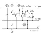
Figure 1. Active shunt regulator for multiple output flyback converters
The circuit operates as follows. While the outputs are both within regulation, resistor divider R14 and R13 bias transistor Q5 on, which keeps Q4 and Q1 turned off. When in this mode of operation, the current through Q5 acts as a small pre-load for the 5 V output.
The nominal difference between the 5 V output and the 3.3 V output is 1.7 V. When the load demands additional current from the 3.3 V output without the same increase in load current being drawn from the 5 V output, its output voltage will increase with respect to that of the 3.3 V output. As that difference exceeds about 100 mV, Q5 becomes biased off, which turns on Q4 and Q1 and allows current to flow from the 5 V output to 3.3 V output. This current lowers the voltage of the 5 V output, which reduces the difference between the two outputs.
The amount of current that flows in Q1 is determined by the difference in the two voltages. Therefore, this circuit helps to keep both outputs in regulation, regardless of their loading; even in the worst case condition of the 3.3 V output being fully loaded while the 5 V output is unloaded. The arrangement of Q5 and Q4 provides temperature compensation, because the VBE temperature variations of each transistor cancel the other out. Diodes D8 and D9 are not required but reduce the dissipation in Q1, which removes the need for it to have a heatsink.
" As that difference exceeds about 100 mV, Q5 becomes biased off, which turns on Q4 and Q1 and allows current to flow from the 5 V output to 3.3 V output".
Please give me a hand if you can figure out .Thanks a lot:smile:.
Here is the article:
Active Shunt Regulator and Pre-load

Figure 1. Active shunt regulator for multiple output flyback converters
The circuit operates as follows. While the outputs are both within regulation, resistor divider R14 and R13 bias transistor Q5 on, which keeps Q4 and Q1 turned off. When in this mode of operation, the current through Q5 acts as a small pre-load for the 5 V output.
The nominal difference between the 5 V output and the 3.3 V output is 1.7 V. When the load demands additional current from the 3.3 V output without the same increase in load current being drawn from the 5 V output, its output voltage will increase with respect to that of the 3.3 V output. As that difference exceeds about 100 mV, Q5 becomes biased off, which turns on Q4 and Q1 and allows current to flow from the 5 V output to 3.3 V output. This current lowers the voltage of the 5 V output, which reduces the difference between the two outputs.
The amount of current that flows in Q1 is determined by the difference in the two voltages. Therefore, this circuit helps to keep both outputs in regulation, regardless of their loading; even in the worst case condition of the 3.3 V output being fully loaded while the 5 V output is unloaded. The arrangement of Q5 and Q4 provides temperature compensation, because the VBE temperature variations of each transistor cancel the other out. Diodes D8 and D9 are not required but reduce the dissipation in Q1, which removes the need for it to have a heatsink.


