fateme91
Member level 2
- Joined
- Nov 18, 2014
- Messages
- 48
- Helped
- 2
- Reputation
- 4
- Reaction score
- 2
- Trophy points
- 18
- Location
- Iran,Mashad
- Activity points
- 349
Hi
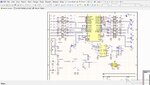
I need to schematic this circuit with an atmega16 :
8 npn analog input with opto
8 npn analog output with opto + transistor
4 digital input (2 ones 0~10 v and 2 ones 4~20 mA)
2 digital output (1 ==> 0~5 v and 1==> 0~10 v)
1 serial port RS232 and 1 port rs485
Can u Help me??
I need to schematic this circuit with an atmega16 :
8 npn analog input with opto
8 npn analog output with opto + transistor
4 digital input (2 ones 0~10 v and 2 ones 4~20 mA)
2 digital output (1 ==> 0~5 v and 1==> 0~10 v)
1 serial port RS232 and 1 port rs485
Can u Help me??