mdpe
Newbie level 3
Hi there! I need some help to get started with a project.
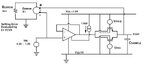
I have to design a simple sample and hold (S/H) stage. The S/H comprises a buffer amplifier and a sampling switch with a sampling capacitor (10MHz). The amplifier buffers the input so that the capacitor voltage must settle to within 1% of ideal final value.
To begin with I want to design the buffer amplifier, I need certain gain so that the settling error is less than the specified value and unity gain bandwidth so that the settling takes place within the defined sample duration.
Should I start with a 2-stages Op amp or 1-stage? I know I need to take into account Ro, output swing, slew rate etc. But i'm a bit lost!
thanks
Attachments
Last edited by a moderator: