mohamis288
Full Member level 3
I want to do transient simulation in ADS. But I encountered with an error shown completely in the following message:
Simulation message:
Status/summary:
In the simulation message at the first line, you can see the following:
In my circuit, I just have 4 DC power supply, and 1 VtRF_pulse power supply which its Rise and fall time is 3 microsecond, and the RF signal is approximately 1.1 GHz signal. What do you think about that? I do not know what does it mean by this amount of bandwidth?
I have added the ADS file in the following link:
ADS file
Also you can download the IC ADS library from the following link:
IC library from NXP website
Do not forget to add PCB layers to your circuit. When you open the project in ADS, make sure to open "myBCproject_lib:firstSchematic".
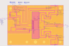
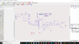
I have attached the schematic picture in the attachment.
Simulation message:
Code:
Highest frequency in data is 1.1e+09 Hz, which is smaller than the maximum source bandwidth 8.72e+09 Hz.
Error detected by hpeesofsim during TRAN analysis `Tran3'.
    Internal timestep 2.45482e-13 too small at time 5.73394e-13.
Status/summary:
Code:
hpeesofsim (*) 490.shp Nov 12 2018, MINT version 4
    (64-bit windows built: Tue Nov 13, 2018 02:20:54 +0000)
Message from hpeesofsim during netlist parsing.
    Booting of Freescale FET2 Power Kit (v1p9) was successful!
TAHB transient MaxTimeStep was not explicitly set; value defaults
to  6.250e-11, which gives 2x oversampling of the highest frequency.

COMPONENT : FET2M2.X4.SNP1.CMP1
    Characterizing to 8 GHz

COMPONENT : FET2M2.X3.SNP1.CMP1
    Characterizing to 8 GHz

COMPONENT : FET2M2.SNP3.CMP1
    Characterizing to 8 GHz

COMPONENT : FET2M2.X2.SNP1.CMP1
    Characterizing to 8 GHz

COMPONENT : FET2M2.SNP2.CMP1
    Characterizing to 8 GHz

COMPONENT : FET2M2.X1.SNP1.CMP1
    Characterizing to 8 GHz

COMPONENT : FET2M2.SNP1.CMP1
    Characterizing to 8 GHz

COMPONENT : FET2M2.SNP4.CMP1
    Characterizing to 8 GHz

COMPONENT : X1.__emcosimModel.em_data
    Characterizing to 1.1 GHz
Pt DC convergence is used.

.


TRAN Tran3[1] <myBCproject_lib:firstSchematic:schematic>   time=(2 ns->4 us)

-------------------------------------------------------------------------------
Simulation finished with errors.
-------------------------------------------------------------------------------

Resource usage:
  Total stopwatch time     =     2.80 seconds.
--------------------
Simulation terminated due to error.
--------------------
In the simulation message at the first line, you can see the following:
Code:
Highest frequency in data is 1.1e+09 Hz, which is smaller than the maximum source bandwidth 8.72e+09 Hz.In my circuit, I just have 4 DC power supply, and 1 VtRF_pulse power supply which its Rise and fall time is 3 microsecond, and the RF signal is approximately 1.1 GHz signal. What do you think about that? I do not know what does it mean by this amount of bandwidth?
I have added the ADS file in the following link:
ADS file
Also you can download the IC ADS library from the following link:
IC library from NXP website
Do not forget to add PCB layers to your circuit. When you open the project in ADS, make sure to open "myBCproject_lib:firstSchematic".
I have attached the schematic picture in the attachment.