Continue to Site

Welcome to EDAboard.com

Welcome to our site! EDAboard.com is an international Electronics Discussion Forum focused on EDA software, circuits, schematics, books, theory, papers, asic, pld, 8051, DSP, Network, RF, Analog Design, PCB, Service Manuals... and a whole lot more! To participate you need to register. Registration is free. Click here to register now.

Highest frequency in data is "yyy" Hz, which is smaller than the maximum source bandwidth "xxx" Hz. - ADS error

Status
Not open for further replies.

mohamis288

Full Member level 3
Joined
Mar 1, 2022
Messages
164
Helped
0
Reputation
0
Reaction score
1
Trophy points
18
Activity points
1,235
I want to do transient simulation in ADS. But I encountered with an error shown completely in the following message:

Simulation message:

Code:
Highest frequency in data is 1.1e+09 Hz, which is smaller than the maximum source bandwidth 8.72e+09 Hz.
Error detected by hpeesofsim during TRAN analysis `Tran3'.
    Internal timestep 2.45482e-13 too small at time 5.73394e-13.

Status/summary:

Code:
hpeesofsim (*) 490.shp Nov 12 2018, MINT version 4
    (64-bit windows built: Tue Nov 13, 2018 02:20:54 +0000)
Message from hpeesofsim during netlist parsing.
    Booting of Freescale FET2 Power Kit (v1p9) was successful!
TAHB transient MaxTimeStep was not explicitly set; value defaults
to  6.250e-11, which gives 2x oversampling of the highest frequency.

COMPONENT : FET2M2.X4.SNP1.CMP1
    Characterizing to 8 GHz

COMPONENT : FET2M2.X3.SNP1.CMP1
    Characterizing to 8 GHz

COMPONENT : FET2M2.SNP3.CMP1
    Characterizing to 8 GHz

COMPONENT : FET2M2.X2.SNP1.CMP1
    Characterizing to 8 GHz

COMPONENT : FET2M2.SNP2.CMP1
    Characterizing to 8 GHz

COMPONENT : FET2M2.X1.SNP1.CMP1
    Characterizing to 8 GHz

COMPONENT : FET2M2.SNP1.CMP1
    Characterizing to 8 GHz

COMPONENT : FET2M2.SNP4.CMP1
    Characterizing to 8 GHz

COMPONENT : X1.__emcosimModel.em_data
    Characterizing to 1.1 GHz
Pt DC convergence is used.

.


TRAN Tran3[1] <myBCproject_lib:firstSchematic:schematic>   time=(2 ns->4 us)

-------------------------------------------------------------------------------
Simulation finished with errors.
-------------------------------------------------------------------------------

Resource usage:
  Total stopwatch time     =     2.80 seconds.
--------------------
Simulation terminated due to error.
--------------------

In the simulation message at the first line, you can see the following:

Code:
Highest frequency in data is 1.1e+09 Hz, which is smaller than the maximum source bandwidth 8.72e+09 Hz.

In my circuit, I just have 4 DC power supply, and 1 VtRF_pulse power supply which its Rise and fall time is 3 microsecond, and the RF signal is approximately 1.1 GHz signal. What do you think about that? I do not know what does it mean by this amount of bandwidth?

I have added the ADS file in the following link:

ADS file

Also you can download the IC ADS library from the following link:

IC library from NXP website

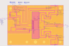
Do not forget to add PCB layers to your circuit. When you open the project in ADS, make sure to open "myBCproject_lib:firstSchematic".

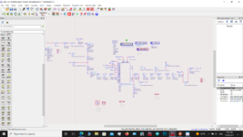
I have attached the schematic picture in the attachment.
 

Attachments

  • schematic.png
    schematic.png
    216.9 KB · Views: 104

Nobody knows answer?
Even when i did not use the cosimulated PCB ( I mean when I just define the transmission line using MLIN component), the error exists yet.
Even if I substitute the current voltage supply with a simple sine voltage supply, the time step error occurs.
 

Attachments

  • Screenshot (259).png
    Screenshot (259).png
    243.2 KB · Views: 130
Last edited:

Why you drive the circuit by a Pulse generator as far as I see. ? What's the reason ?
Hello @BigBoss
My circuit is triggered by a RF pulsed signal. As I said before, even if I use a sine voltage, time step error occurs. As soon as possible, I will upload my schematic.
--- Updated ---

Here is the schematic file. Do not forget to add definition files, which are available in "simulation" document to the ADS workspace.
 

Attachments

  • example.rar
    41.5 MB · Views: 108
Last edited:

Hello @BigBoss
My circuit is triggered by a RF pulsed signal. As I said before, even if I use a sine voltage, time step error occurs. As soon as possible, I will upload my schematic.
--- Updated ---

Here is the schematic file. Do not forget to add definition files, which are available in "simulation" document to the ADS workspace.
Your thinking is wrong.
You have to drive the Amplifier with sinusoidal signal in any case. Because hard transient signals, ringings, overshoots etc. may occur due to capacitive, inductive elements on the road. So, you'd better to use sinusoidal first then move forward a step ahead.
 

Your thinking is wrong.
You have to drive the Amplifier with sinusoidal signal in any case. Because hard transient signals, ringings, overshoots etc. may occur due to capacitive, inductive elements on the road. So, you'd better to use sinusoidal first then move forward a step ahead.
Nobody knows answer?
Even when i did not use the cosimulated PCB ( I mean when I just define the transmission line using MLIN component), the error exists yet.
Even if I substitute the current voltage supply with a simple sine voltage supply, the time step error occurs.
I have done simulation with a simple sine voltage supply previously. But , this time I have done it by implementing all the point mentioned in the following link: I have added an ultra-small capacitor at all node, set the convolution, set the convolution max frequency at 10-100 GHz (because my carrier frequency is nearly 1 GHz), set the maxTimeStep 1-100 ps.

https://www.edaboard.com/threads/ads-error-message-the-internal-timestep-is-too-smaller-help.143709/

After doing all, transient simulation started but after 7 seconds, the same Time Step error message appeared.

I think placing the log message would be helpful.
 

Attachments

  • error txt .txt
    52.6 KB · Views: 103

NXP's Design Kit is not compatible with the version of ADS which I've actually been using.
If you have an opportunity to use Cadence AWR, I recommend you to use it because I tried a sample form NXP, there is no problem at all. The basic simulation results are accordingly fit to datasheet information.
Think about it..
Hello,
Thank you for your answer. In fact, my ADS version in 2019 and the interesting point is that IC library can not be used with ADS2021 and ADS2022.
Also I do not have any problem with s-parameter simulation and all the results are as per the datasheet. but it is 2 months which I have tried to do transient simulation, however unfortunately, I have failed every time.

Thank you again
 

NXP's Design Kit is not compatible with the version of ADS which I've actually been using.
If you have an opportunity to use Cadence AWR, I recommend you to use it because I tried a sample form NXP, there is no problem at all. The basic simulation results are accordingly fit to datasheet information.
Think about it..
Hello again,
Can you please answer my questio:
Have you done transient simulation (not s-parameter simulation) on sample example from NXP? Can you please give that sample example please?
 

Hello again,
Can you please answer my questio:
Have you done transient simulation (not s-parameter simulation) on sample example from NXP? Can you please give that sample example please?
I have done this simulation in Cadence AWR and there is no problem at all.
 

Attachments

  • NXP_Test_sch.pdf
    145.7 KB · Views: 109
  • NXP_Test_power.pdf
    161.2 KB · Views: 100
  • NXP_Test_transient.pdf
    162.5 KB · Views: 113
Hello,
Thank you for your answer. In fact, my ADS version in 2019 and the interesting point is that IC library can not be used with ADS2021 and ADS2022.
Also I do not have any problem with s-parameter simulation and all the results are as per the datasheet. but it is 2 months which I have tried to do transient simulation, however unfortunately, I have failed every time.

Thank you again
Hello,
NXP model does not have any problem. In fact, without any transmission line (IC ADS model alone without any other connection and wire), simulation is done successfully. But, if I use the original schematic and remove MSTEP component and also set convolution in transient simulation as strict mode and plus a couple of other changes, the simulation is done till 73% and then, It gives time step error. Considering that, there is not any problem with IC model, do you have any other solution?
As I said I have done all the advices in the following link:

https://www.edaboard.com/threads/ads-error-message-the-internal-timestep-is-too-smaller-help.143709/

simulation parameter:
start = 0
stop=200ps
maxTimeStep=0.1 ps

Thank you
 

Status
Not open for further replies.

Part and Inventory Search

Welcome to EDABoard.com

Sponsor

Back
Top