Continue to Site

Welcome to EDAboard.com

Welcome to our site! EDAboard.com is an international Electronics Discussion Forum focused on EDA software, circuits, schematics, books, theory, papers, asic, pld, 8051, DSP, Network, RF, Analog Design, PCB, Service Manuals... and a whole lot more! To participate you need to register. Registration is free. Click here to register now.

High snubber dissipation in 300W pushpull?

Status
Not open for further replies.

cupoftea

Advanced Member level 5
Joined
Jun 13, 2021
Messages
2,602
Helped
54
Reputation
108
Reaction score
115
Trophy points
63
Activity points
13,643
Hi,
We have received from cust a synchronous pushpull 300w, 24vin, 32vout, 300w, 300khz, Planar txformer=ER32 at 1:2 (LP=28.6uH).

We’ve got to make it work. Its got no snubbers on the pri and sec FETs /Diodes. We will wire some in.
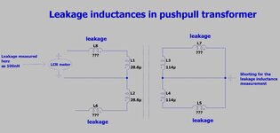
The planar txformer manufacturer tells us they measured 100nH of leakage L on one half of the primary, with all three secondary terminations shorted.
As such, do you agree, this must mean that leakage in each primary “half” is 200nH? Also, that leakage in each secondary “half” must be 400nH?

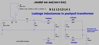
The attached LTspice is showing 2.6W total in the sec snubbers, and 11.6W total in the primary snubbers.
This is an awful lot. Do you believe that it is actually 200nH of leakage L in each primary half?

(my apologies, as i asked on this similar-ish subject recently, but not on the actual leakage figures, so there was no answers on this)

pushpull300w_221216.jpg
 

Attachments

  • pupull300w_221216.zip
    2.8 KB · Views: 81

Woops sorry, no, i was incorrect.....the two secondary "half coils" will be seen as in parallel from the primary "half coil"....as such it boils down to a 1:1 transformer....and the "seen" leakage will be Lm // n^2 Llks.....and since NP/NS is now effectively 1;1, then Llkp = Lm // Llks = 100nH.
Would you agree?
 

oops...so, again, the situation is as in the attached. Soon, will test it in LTspice to see if the theory is correct...the mystery leakage inductances?....will probably get the sim resonating with a known capacitor, and see the resonant frequency, hence calculate the leakage.
 

Attachments

  • Pushpull transformer leakage.jpg
    Pushpull transformer leakage.jpg
    141.3 KB · Views: 81
  • Pushpull transformer leakage.zip
    817 bytes · Views: 81

Assuming all 4 windings are equally coupled (unlikely in reality, but a fair first order estimation). If you measure 100 nH with three other windings shorted, you get 75 nH per winding (or a respective transformed value for unequal winding ratio).

Because transformers have rarely exactly symmetric leakage, I prefer to identify individual leakage inductance contributions, if possible.
 
Hi FvM, thankyou very much, i believe you to be correct...and the attached LTspice sim confirms your statement.
I did it here and put 65nH for primary leakage, and i then made sec leakage 4x that...so made it 260nH....and that gives the 100nH when measured at the half primary coil with three sec terminals shorted.
So this appears to have cracked it?

Actually, these figures are very close to Easy Peasy's kindly giving of a quick , rough estimate a few weeks back...where i believe he deliberately ignored L(mag), knowing it to be small, and for informations sake, no need for him to calculate it out in full.

Pretty low, but this is a planar transformer, so i guess they can make leakage very low........the "demon from the deep" might be high interwinding capacitance of course......and i wonder how that demon may have afflicted the leakage inductance measurement?
 

Attachments

  • Leakage sim calc.jpg
    Leakage sim calc.jpg
    162.4 KB · Views: 78
  • Pushpull transformer leakage_2.zip
    1.1 KB · Views: 91
Last edited:

If you want to know the exact distribution of leakage inductance and other parameters (e.g. capacitances) of your transformer, you either need to measure it or estimate it in finite element modelling. As ER32 palanar transformer has almost round windings, you can get quite accurate results in axisymmetric simulation setup, e.g. with free FEMM tool.
 
just looking at the schematic near the top

any snubbers should be tightly fitted across the fets and/or diodes

not far away across the Tx wdgs ...
 
just looking at the schematic near the top

any snubbers should be tightly fitted across the fets and/or diodes

not far away across the Tx wdgs ...
Thanks, the pri side snubbers are actually across the windings, as they are kind of "flyback RCD style"-ish.
The sec side snubbers we couldnt do like this, so they are across the FETs/diodes.....but i have to confess on the PCB, they are wired in, and the sec fets/diodes are on bottom side, and we cant get them close to the fets/diodes there......so the snubbers are soldered to the txformer terminals on the sec side....they are on little PCBs on the end of twisted pair wire.
 

Status
Not open for further replies.

Similar threads

Part and Inventory Search

Welcome to EDABoard.com

Sponsor

Back
Top