cupoftea
Advanced Member level 5
Hi,
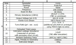
We have been given a 300W synchronous Pushpull to bring up by a customer.
24VIN, 32Vout, 225kHz, isolated.
Transformer is 1:2.
Its planar and the manufacturer tells us the leakage L is 1.2uH “measured at primary with sec shorted”.
The attached planar spec, is from the Planar Company that designed this planar transformer for our customer.
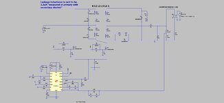
The thing is, the peak primary current is 21A. …and with 600nH of leakage L in that primary “half”, that means an energy of 0.5xLxI^2, and a power dissipation from that leakage inductance (in the primary TVS) of some 15W. ( from 0.5 x L x I^2 x f). The simulation confirms this level of dissipation in the snubber (TVS).
That’s way too much as you can tell.
Would you agree, the Pushpull cannot be used for these levels of leakage inductance? There’s nowhere for the leakage inductance current to flow, when a primary FET turns off. I wonder how on earth the pushpull even exists above very low powers. I mean with planar you can (in theory) get very low levels of leakage inductance….but at the cost of large interwinding capacitance. -And we don’t particularly want such large stray C in a hard-switched converter. I believe we will request a re-do as a Full Bridge. Would you concur?
LTspice and jpeg attached
We have been given a 300W synchronous Pushpull to bring up by a customer.
24VIN, 32Vout, 225kHz, isolated.
Transformer is 1:2.
Its planar and the manufacturer tells us the leakage L is 1.2uH “measured at primary with sec shorted”.
The attached planar spec, is from the Planar Company that designed this planar transformer for our customer.
The thing is, the peak primary current is 21A. …and with 600nH of leakage L in that primary “half”, that means an energy of 0.5xLxI^2, and a power dissipation from that leakage inductance (in the primary TVS) of some 15W. ( from 0.5 x L x I^2 x f). The simulation confirms this level of dissipation in the snubber (TVS).
That’s way too much as you can tell.
Would you agree, the Pushpull cannot be used for these levels of leakage inductance? There’s nowhere for the leakage inductance current to flow, when a primary FET turns off. I wonder how on earth the pushpull even exists above very low powers. I mean with planar you can (in theory) get very low levels of leakage inductance….but at the cost of large interwinding capacitance. -And we don’t particularly want such large stray C in a hard-switched converter. I believe we will request a re-do as a Full Bridge. Would you concur?
LTspice and jpeg attached
Attachments
Last edited: