cupoftea
Advanced Member level 5
Hi,
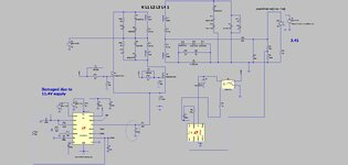
We are doing a 300W pushpull
24vin, 32vout, 350khz.
(as atatched LTspice and jpeg).
The attached is how we have it, with opto feedback exactly as shown......its just giving 2.56v on the output....the opto driver (LT1431) is pulling so much current through the opto_diode that the output voltage is only 2.56v.
Incidentally, i once got rid of the opto feedback, and did direct vout divider feedback back to the LTC3723-1 (obviosly non isolated), and it THEN works fine.....its just when we put in the opto feedback like the attached it doesnt work........as discussed, the opto driver is pulling too much current through the opto diode unfortunately.
Do you know what might be wrong?...i changed the LT1431 and it still doesnt work.
..PS, i know the attached sim is unstable, but at least it gives >2.56 vout.....we could work on the instability, but at the moment, the opto is just braking the beck out of it, for some reason....
Attachments
Last edited: