Continue to Site

Welcome to EDAboard.com

Welcome to our site! EDAboard.com is an international Electronics Discussion Forum focused on EDA software, circuits, schematics, books, theory, papers, asic, pld, 8051, DSP, Network, RF, Analog Design, PCB, Service Manuals... and a whole lot more! To participate you need to register. Registration is free. Click here to register now.

High Frequency counter

Status
Not open for further replies.

Mohamed Slama

Member level 4
Joined
Nov 8, 2013
Messages
72
Helped
0
Reputation
0
Reaction score
0
Trophy points
6
Activity points
443
Hi
I have done 50 MHZ frequency counter by pic 16f877A and 20MHZ crystal.

My question : can i convert it to 200 MHZ by divide the input frequency to a certin value ??

If yes , any another steps are required ?

thank u in advance
 

All you have to do is scale the signal by dividing it. If you divide by 4, as long as the divider is capable of running at 200MHz it will produce 50MHz output to the existing counter. If you want to make it more user friendly, multiply the result by 4 in software so your readout shows real MHz again. The only problem will be that by dividing by 4 you lose some precision because the smallest unit you can measure becomes 4 times larger, in other words it would take 4Hz change in frequency to show as 1 digit change on your display.

Brian.
 

Probably unnecessary to mention due to being an implicit concept, but adoption of frequency division by factors multiple of 2, offers the simplicity for implement that scaling employing solely cascaded flip-flops.


+++
 

thank u betwixt

any suggests about changing pic or another method to measure in precise ?
 

Maybe I am missing something but to directly count 50 MHz with the PIC isn't a fairly large, internal pre-scale required (16?)? Is adding another factor of 4 that much different? Also, once you add some external FFs, should a counter chip with SPI or low pin count interface be considered? Then, perhaps the measurement can be done with no pre-scale and have the most accuracy. Please correct me if I am wrong about directly measuring 50 MHz.
 

In order to allow us give you a more precise answer, you need provide more details concerning behavior of signal to be acquired, such as its variation range along time and also the rate displacement.

Even a long term counting could improve precision. For instance, if you consider overflowing n-times a counter on its entire magnitude ( e.g a 8 bits one counting from 0 up to 255 ), and divide it for elapsed time, you can get as result an extended precision number, which could compensate mentioned loss on pre-scaler.


+++
 

Posts #5 and #6 are both correct. The counter hardware in most PICs can run at 50MHz or more and is not dependant on the clock frequency, it's the gating time that is difficult to control accurately. It is easy to extend the range of the internal timer registers by enabling their interrupts and incrementing a counter each time one occurs, the counter becomes the highest byte of the pulse count. For example, a single byte counter (8 bits) incremented at each TMR1 interrupt will extend it's count range from 0 - 65535 up to 0 - 16777216 while maintaining full accuracy.

So if an external frequency divider was used, and the gate (measurement window) was adjusted proportionately, the range can be expanded without losing accuracy.

Brian.
 

hello,


Less than 50MHZ is the maximum frequency given by Microchip for counting on RA4 Timer0 input..
But on some chip we can reach 50Mhz, on Other not ...

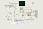
I used a specific pre-divider to count up to 433Mhz ( not tested for upper values)
MB506 divide by 256 up to 1Ghz !
but impedance input is as low as 50 ohms !


you can see details on my web page.

Freq_WCT7_LCD4b_1Ghz_1.jpg
 

That's a nice design Paulfujo.

One of the things I want to build when I have time is a 2GHz+ counter, I have the parts but not the time!

I use PIC16F1847 in several projects (it is pin compatible with 16F84) and it has a nice feature of having a gated TMR1 counter. It means you can feed the external signal into the TMR1 clock input and use TMR0 to control the gating time. It makes frequency counting very easy with no external gates needed. I have about 100 spare MC12034A ICs in stock, left over from an old project, they are almost the same as the MB506 but only divide by 32/33/64/65 and they are more sensitive, they should make ideal prescalers. Most work up to about 2.6GHz

Brian.

Brian.
 

Status
Not open for further replies.

Part and Inventory Search

Welcome to EDABoard.com

Sponsor

Back
Top