Continue to Site

Welcome to EDAboard.com

Welcome to our site! EDAboard.com is an international Electronics Discussion Forum focused on EDA software, circuits, schematics, books, theory, papers, asic, pld, 8051, DSP, Network, RF, Analog Design, PCB, Service Manuals... and a whole lot more! To participate you need to register. Registration is free. Click here to register now.

HFSS: The value for radius of surrounding sphere in Hertzian dipole source

Status
Not open for further replies.

fsky

Newbie level 4
Joined
Sep 28, 2011
Messages
7
Helped
0
Reputation
0
Reaction score
0
Trophy points
1,281
Activity points
1,337
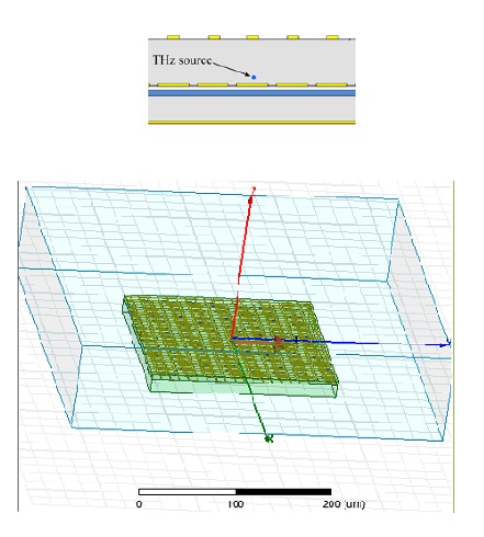
Hi all, Can anybody explain what the surrounding sphere is meant to be and how the value for that is considered?

The freq. band of my simulation is 1-6 THz and the paper says the source is a half wavelength electrical Hertzian dipole...
 

Hi fsky,

Usually, one wants the radiation boundary to extend one-quarter wavelength past the largest radius of the antenna. This is to ensure that the radiated fields are plane-wave-like enough to be absorbed properly.
 
  • Like
Reactions: fsky

    fsky

    Points: 2
    Helpful Answer Positive Rating
Hi fsky,

Usually, one wants the radiation boundary to extend one-quarter wavelength past the largest radius of the antenna. This is to ensure that the radiated fields are plane-wave-like enough to be absorbed properly.

Thanks PlanarMetamaterials for your reply and helping. Well, I didn't understand what you said completely... what do you mean by antenna radius, it is the size of excitation source or the whole structure acting as an antenna? what is the difference between the value of surrounding sphere radius and the airbox which encloses the whole structure? I didn't understand surrounding sphere for which HFSS says the fields inside and on the surface are considered the same... :(


I am trying to simulate a fabry-perot like structure which is a leaky-wave antenna. For the THz source the paper suggests a half wavelength electrical Hertzian dipole above the high impedance structure and below the FSS in the superstrate(er=2.5)... I put my whole structure of 20*20 unit elements (200*200um, each unitcell is 10*10um) in an air box which size is 400*400um and the height is 5 times the height of the unit-cell (Is it needed to be that large? or just to enclose the structure is enough) and assigned the radiation boundary to the top and surrounding faces. I am not sure about the THz source exact place and I put it in the middle and a few ums above the HIS ground...(what about matching in this case of excitation, correct me please if I am totally wrong) If I consider 3THz as the center freq. could you please tell me the values for I*dipole length oriented in y axis and the radius of surrounding sphere?

I am sorry to ask so many questions...:oops: There is no one around to give me a hint nor I could figure out by myself and the simulation takes so much time to understand my errors after checking the results. I really appreciate your time...


Well, I didn't understand what you said completely... what do you mean by antenna radius, it is the size of excitation source or the whole structure acting as an antenna?

The entire antenna.

what is the difference between the value of surrounding sphere radius and the airbox which encloses the whole structure? I didn't understand surrounding sphere for which HFSS says the fields inside and on the surface are considered the same... :(

The radiation boundary will be on the surface of the airbox. So they are related in size.

I am trying to simulate a fabry-perot like structure which is a leaky-wave antenna.

Umm... can you explain that differently. I'm not sure how a FP device would/could behave like a leaky-wave antenna.

For the THz source the paper suggests a half wavelength electrical Hertzian dipole above the high impedance structure and below the FSS in the superstrate(er=2.5)... I put my whole structure of 20*20 unit elements (200*200um, each unitcell is 10*10um) in an air box which size is 400*400um and the height is 5 times the height of the unit-cell (Is it needed to be that large? or just to enclose the structure is enough) and assigned the radiation boundary to the top and surrounding faces. I am not sure about the THz source exact place and I put it in the middle and a few ums above the HIS ground...(what about matching in this case of excitation, correct me please if I am totally wrong) If I consider 3THz as the center freq. could you please tell me the values for I*dipole length oriented in y axis and the radius of surrounding sphere?

I can't help you with your antenna or surface, but I can tell you that if the antenna is half a wavelength, then you need to make sure that the distance from any point on the surface/antenna to the outer edge of the air box is at least half that distance.
 

Hi fsky,

Maybe you could give us the title of the paper then someone may find a clue.
a)For the dipole, I would try the radius 0.01 wavelength as it may be convenient for fabrication?
b)If the impedance matching is not good, it may not only caused by the dipole, you may need to refer to some fabry-perot antenna papers.
c)if the patten is not so directive, maybe the HIS or PRS is well designed. you may need to check the reflection coefficients using floquet mode in HFSS/CST
 
  • Like
Reactions: fsky

    fsky

    Points: 2
    Helpful Answer Positive Rating
Hi fsky,

Maybe you could give us the title of the paper then someone may find a clue.
a)For the dipole, I would try the radius 0.01 wavelength as it may be convenient for fabrication?
b)If the impedance matching is not good, it may not only caused by the dipole, you may need to refer to some fabry-perot antenna papers.
c)if the patten is not so directive, maybe the HIS or PRS is well designed. you may need to check the reflection coefficients using floquet mode in HFSS/CST

if the patten is not so directive, maybe the HIS or PRS is not well designed. you may need to check the reflection coefficients of the unit cells using floquet mode in HFSS
 

Umm... can you explain that differently. I'm not sure how a FP device would/could behave like a leaky-wave antenna.
Thanks for your response! But it seems that much smaller radius is needed for the surrounding sphere. Well, about the difference between this type of leaky-wave antenna and the fabry-perot structure, the point is that in Fabry-perot there are two conducting surfaces and a dielectric between but in the mentioned leaky-wave antenna the upper surface is partially reflecting so that the waves could leak out from it thus it is leaky-wave. By the proper selection of the height of superstrates high directivity is achievable.
 

Hi fsky,

Maybe you could give us the title of the paper then someone may find a clue.
a)For the dipole, I would try the radius 0.01 wavelength as it may be convenient for fabrication?
b)If the impedance matching is not good, it may not only caused by the dipole, you may need to refer to some fabry-perot antenna papers.
c)if the patten is not so directive, maybe the HIS or PRS is well designed. you may need to check the reflection coefficients using floquet mode in HFSS/CST

Hi Chao,

I really appreciate your help. I had checked the HIS results and they are okay and after that I determined the height of cavity (5.5 um) for proper resonant at 3 THz. However, for the entire structure consisting of a HIS ground, superstrate as the cavity and FSS as the top surface, I am not sure about the place of dipole in the z direction?? (I wonder whether we consider matching for these types of antennas or we do not. I do not know what parameters should be considered if matching should be noticed.) I put the dipole 0.1 um above the HIS and select the radius of surrounding sphere as 10 um which is 0.1 free space wavelength. The outcomes in rETotal plots, one resembles almost the H-plane radiation pattern but the other differs from E-plane greatly specially in the number of lobes. I have attached my structure in the first post.

- - - Updated - - -

Hi fsky,
a)For the dipole, I would try the radius 0.01 wavelength as it may be convenient for fabrication?

BTW could you tell what is the surrounding sphere of dipole for which HFSS says the fields inside and on the surface are considered the same?
 

Status
Not open for further replies.

Part and Inventory Search

Welcome to EDABoard.com

Sponsor

Back
Top