Algregious
Newbie
Hello,
I am trying to obtain the S11 parameters from an interrogator antenna to determine the resonant frequency of the component being interrogated. I know this is probably a pretty unconventional method of modeling, but it is something that we wanted to see if it would work and agree with our experiments.
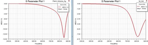
The component is a 500MHz patch antenna; I have simulated the structure and I can confirm that its S11 dips at ~500MHz. I've taken that model and modelled an arbitrary antenna above it to see if I could capture the same results.
Has anyone ever tried this or might know some ways to improve the model? The new S11 does have a dip at ~500MHz but it seems to me that the interrogator's resonance overshadows it. Also, I am having trouble deciding a solution type and port setup; I am not an EE, but actually a third year ME intern.
Just for looking ahead, we plan to interrogate a much smaller passive sensor, so if anyone could give some tips regarding port setup and size of the interrogator antenna, I'd appreciate much!
I've attached a zip that contains the HFSS archive.
Thanks for any help!
I am trying to obtain the S11 parameters from an interrogator antenna to determine the resonant frequency of the component being interrogated. I know this is probably a pretty unconventional method of modeling, but it is something that we wanted to see if it would work and agree with our experiments.
The component is a 500MHz patch antenna; I have simulated the structure and I can confirm that its S11 dips at ~500MHz. I've taken that model and modelled an arbitrary antenna above it to see if I could capture the same results.
Has anyone ever tried this or might know some ways to improve the model? The new S11 does have a dip at ~500MHz but it seems to me that the interrogator's resonance overshadows it. Also, I am having trouble deciding a solution type and port setup; I am not an EE, but actually a third year ME intern.
Just for looking ahead, we plan to interrogate a much smaller passive sensor, so if anyone could give some tips regarding port setup and size of the interrogator antenna, I'd appreciate much!
I've attached a zip that contains the HFSS archive.
Thanks for any help!