Externet
Advanced Member level 2
- Joined
- Jan 29, 2004
- Messages
- 579
- Helped
- 28
- Reputation
- 58
- Reaction score
- 29
- Trophy points
- 1,308
- Location
- Mideast US
- Activity points
- 5,669
Hello all.
By mid eighties, I installed a couple of uncommon antennas on 2 large yatchs for communication on all HF marine bands and all HF amateur bands.

It performed surprisingly well. I did not compare to other as no other was comparable; all others requiered a tuner/matcher for every frequency chosen and this provided communication half globe away from a 100W Kenwood TS430S on SSB. There was not much improvement to ask. It just worked superb.
It looked like a 10cm x 10cm x 4cm hard aluminium box but not the one in the picture below. Fed to its single SO-239. Very secured to an aluminium surface (electrically part of hull) with intimate 'grounding' contact, and a single long wire extended hooked to anywhere on insulated end.

I was told much later it had a 100 watt 50 ohm resistor inside and the long wire element insulator and nothing else.
I assume the resistor presented resistive 50 ohm showing excellent SWR at all frequencies and the radiating long wire performed on a 'leftover' radiating power.
- What is your comment about that design 'strategy' this antenna had; is there others similar using the same 'trick' ?
- Would you know what brand was it ? Have not seen it in many decades.
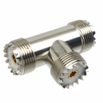
- What would happen if a HF transceiver 50 ohm is connected to a 'T' with one arm of the 'T' to a 50 Ohm dummy load and the other arm of the 'T' to a long as practical wire ?

-Images borrowed from the web-
By mid eighties, I installed a couple of uncommon antennas on 2 large yatchs for communication on all HF marine bands and all HF amateur bands.
It performed surprisingly well. I did not compare to other as no other was comparable; all others requiered a tuner/matcher for every frequency chosen and this provided communication half globe away from a 100W Kenwood TS430S on SSB. There was not much improvement to ask. It just worked superb.
It looked like a 10cm x 10cm x 4cm hard aluminium box but not the one in the picture below. Fed to its single SO-239. Very secured to an aluminium surface (electrically part of hull) with intimate 'grounding' contact, and a single long wire extended hooked to anywhere on insulated end.
I was told much later it had a 100 watt 50 ohm resistor inside and the long wire element insulator and nothing else.
I assume the resistor presented resistive 50 ohm showing excellent SWR at all frequencies and the radiating long wire performed on a 'leftover' radiating power.
- What is your comment about that design 'strategy' this antenna had; is there others similar using the same 'trick' ?
- Would you know what brand was it ? Have not seen it in many decades.
- What would happen if a HF transceiver 50 ohm is connected to a 'T' with one arm of the 'T' to a 50 Ohm dummy load and the other arm of the 'T' to a long as practical wire ?
-Images borrowed from the web-