- Joined
- Jan 22, 2008
- Messages
- 52,383
- Helped
- 14,746
- Reputation
- 29,774
- Reaction score
- 14,089
- Trophy points
- 1,393
- Location
- Bochum, Germany
- Activity points
- 297,931
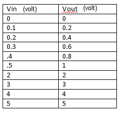
I hope so. But for the sake of clarity you should really show a diagram of expected output versus input voltage, or may be a table.you get what i want to do.