Continue to Site

Welcome to EDAboard.com

Welcome to our site! EDAboard.com is an international Electronics Discussion Forum focused on EDA software, circuits, schematics, books, theory, papers, asic, pld, 8051, DSP, Network, RF, Analog Design, PCB, Service Manuals... and a whole lot more! To participate you need to register. Registration is free. Click here to register now.

HELP single source supply for differential amplifier!

Status
Not open for further replies.

bubble_d

Junior Member level 3
Joined
Sep 12, 2012
Messages
25
Helped
0
Reputation
0
Reaction score
0
Trophy points
1,281
Visit site
Activity points
1,483
Hi Edaboard,

I am building 4 single source differential amplifiers which read 4 separate lithium Ion batteries which can be adjusted via a 100k potentiometer. I am having a lot of issues with the single source so far.

Here is my Multisim Schematic.
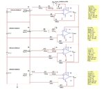
Design.jpg

At first I attached it exactly as the schematic, but I remembered that I need to create virtual ground by dividing the 9 volt supply and using that as my virtual ground. At this point I am working only with the bottom op-amp which is connected to ground..

When I connect all my ground to virtual ground (Except pin 4 of the op-amp which goes to ground) and I from pin 6 to virtual ground I get 4.11V which is unaffected by battery alone, I.E if I pull the battery it it gives me the same value!

Gah this is getting frustrating! Can anyone help me?
 

I spent a few minutes reading your post and looking at the schematic but I couldn't understand exactly what it is that you want to do. Without bothering about whether your design is correct or not, can you give a clearer explanation of what you're trying to do?
 

You are applying 14.8 V to the input of the topmost op amp. This is greater than the supply rail. That could create a problem.

Edit:

Now I see the volt level can reach 7.4 on both inputs of the topmost op amp. The second op amp can get 5.5 V at both its inputs. It still can cause a problem.
 
Last edited:

Sorry,

Here is what I need to do.

I need to simulate a single battery cell which is made up of 4 Lithium Ion battery cells. So the way I did this was but connecting 4 3.7V (Actually gives me 4.15V) batteries in series then using a differential amplifier read the voltage across the battery cell.
I also included a potentiometer between the battery and the op-amp such that I can manually change the output of a module to show an unbalanced battery cell. I will be connecting this whole setup to a explorer 16 micro-controller board and use the ADC to read the 4 outputs (I.E output of the differential amplifiers) which will show me the voltage of each individual cell.

I chose my Vcc as 9 volts because that is the highest available voltage from given by the micro-controller.

- - - Updated - - -

After the resistors the voltage entering the 2 & 3 pins of the op-amp is 7.4V max. It only decreases from that point on.
 

741 can't work correctly because the output can't go near the power supply voltages and the input range can be a problem too.
A different opamp that can go down to 0 level should solve that.
Can you try lm358?
Note that it can go down to 0 but no up to Vcc so the topmost diff amp may still not work properly.
A rail to rail model should solve the problem.

I also noticed that with the third and fourth battery the + input (referenced to gnd) is higher than the 9v supply, this can't work

Edit: ignore the grey parts
 

For the time being, in this phase of initial development, it will be easier if you use a bipolar supply consisting of two 9V batteries, with a real ground in between them.

Later when you get the outputs acting as you expect, you can reduce the lower supply to 0V, and see if things still work okay.

Your topmost op amp should have a positive supply which is greater than 7.4V.

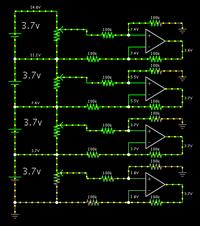
My simulation shows your setup will work. (I can't be sure whether Falstad's simulator gives the op amps an over-simplified power supply.)

Screenshot:


I have already done this but with +- 15V supply (And It worked). I will redo this with 9v supply to see how it reacts.


I will only have access to a power supply on Monday when I get back to school. Thank you.
 

For +-15 it will work fine but the problem is when you use a single supply for 741, with 9v single supply the usable range should be about 2v to 7v, unfortunately the simulation models don't reflect that very accurately.
 

Status
Not open for further replies.

Part and Inventory Search

Welcome to EDABoard.com

Sponsor

Back
Top