Continue to Site

Welcome to EDAboard.com

Welcome to our site! EDAboard.com is an international Electronics Discussion Forum focused on EDA software, circuits, schematics, books, theory, papers, asic, pld, 8051, DSP, Network, RF, Analog Design, PCB, Service Manuals... and a whole lot more! To participate you need to register. Registration is free. Click here to register now.

[SOLVED] Help needed: a simple circuit for car Ignition control

Status
Not open for further replies.

nidclt

Junior Member level 2
Joined
Aug 14, 2012
Messages
24
Helped
0
Reputation
0
Reaction score
0
Trophy points
1,281
Location
Calicut, India
Activity points
1,469
Hi guys, I'm on a project of adding a Fingerprint based ignition system on my car. I've a fingerprint module which will store some finger prints, it will will give a half second pulse(5volt) if the correct fingerprint is detected. I sourced this module from a lock(Adel trinity 788). So the module will give out another half second 5volt pulse after 3 seconds(actually to close the door, which is not needed in my case)

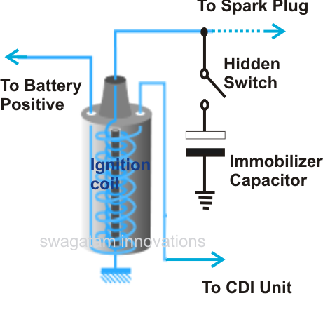
Now let me come to my project. I need to make a 'circuit' that will detect the first pulse from fingerprint module and a relay coil must be activated(to switch ON the ignition of car). This circuit should neglect the second pulse from fingerprint module that comes after 3 seconds. I'm adding a push button to start the engine. Then about the switching off of ignition. The finger print module will send out two pulse as before when I use the finger print module to switch the ignition OFF.The circuit should accept the first signal and the relay should be deactivated to turn the ignition OFF.

This circuit has to be connected to the 'Handbrake' signal of the car. So the finger print works only when the Handbrake is engaged, so I will start and stop engine only when the handbrake is engaged.

I know it will be very simple for experienced guys here, but I'm a bit low with 555 IC and astable multivibrators.

About the voltage part, Finger print module works at 6V and my car voltage is around 12~13.5v

Can anyone please design a circuit that fulfill this needs. Any help is much appreciated.
 

My friend where are you living in Bronx ? :shock:

Did you consider rather to use some hidden buttons, say two, and you need to press right combinations of them.

But what will stop thief to open hood and add plus wire direct on HV coil (bobina) ?

I remember that people when whant to save car, remove distribution arm or complete distribution hat from car. :-D
 
Last edited:

My friend where are you living in Bronx ? :shock:

I'm from India! :cool:

Hey, it's not for security thing! It's more like hobby. Also I don't think any thief will be interested in my 2001 model Daewoo Matiz:p

Adding more buttons won't do justice, I'm trying to avoid the inconvenience of having the key with me always. So I think adding additional buttons won't help here.
Anyway thanks for your reply
 
Last edited:

Only this can save you :

https://www.youtube.com/watch?v=ryV8kyFwwYA


See this :

Car+Immobilzer.png


**broken link removed**
 
Last edited:

View attachment magvitron.zip


here's the circuit i made up. its kind of crude , but here goes.The first 555 is used as the monostable multivibrator @ 3 sec, do you need not to worry about the second pulse. the trigger pulse is given to the monostable after inversion using a simple transistor. the pulse from the monostable is used to drive a toggle flip flop. so after turning the engine on, you can turn off. the relay can be used to turn the ignition on / off.
attached proteus file.
xxxc.jpg
btw im from quilon ;-)
 

Attachments

  • xxxc.jpg
    xxxc.jpg
    223.5 KB · Views: 156
View attachment 78626


here's the circuit i made up. its kind of crude , but here goes.The first 555 is used as the monostable multivibrator @ 3 sec, do you need not to worry about the second pulse. the trigger pulse is given to the monostable after inversion using a simple transistor. the pulse from the monostable is used to drive a toggle flip flop. so after turning the engine on, you can turn off. the relay can be used to turn the ignition on / off.
attached proteus file.
View attachment 78625
btw im from quilon ;-)

Thanks a lot Magvitron, much appreciated for the quick reply.
Can you please include the Handbrake part(12v from hand brake engaged light). The finger print module should get power only when it is engaged. Also can you include the power supply for the fingerprint module in it like using LM7906 or so. Once I get these I'm heading straight to electronic components shop.

BTW I'm from Calicut:) Thanks again!
 

xxxc.jpg
here's the thing, if the handbrake is enabled, the reset is disabled in 555 else its in reset. btw sorry for the delay, i first thought of ANDing the signals, but this is better. Happy onam!!
 
View attachment 78629
here's the thing, if the handbrake is enabled, the reset is disabled in 555 else its in reset. btw sorry for the delay, i first thought of ANDing the signals, but this is better. Happy onam!!

Thanks a lot Manu. The diodes are IN4001 or IN4007 right?

Happy Onam!
 

yeah.. its just for free wheeling and protection. better use 1n 4007. Its cheap 50p per piece.

Components I'll be buying:

IC:
NE555 - 1 No.
CD4013 - 1 No.
LM7806 - 1 No.

Transistors:
BC548 - 3 Nos.

Diodes:
IN4007: - 2 Nos.

Capacitors:

.01uF - 2 Nos.
1uF - 1 No.
100uF - 1 No.

Resistors:
1K - 1 No.
10K - 4 Nos.
2.2K - 2 Nos.
36K - 1 No.
47K - 1 No.
100K - 1 No.

Relay:
12V 40Amps for Ignition

Will let you know the results soon!
 
Last edited:

hey im afraid i did'nt see this..
(12v from hand brake engaged light
i thot youre gonna use a switch, as per simulation. the fomer might work, but this is better suited .. the extra bit is a transistor and 2 resistors , one 100k and a 47k.hope you wont mind.

xxxc.jpg

an extra bit of circuit may be needed here, for protection.
 

Attachments

  • xxxc.jpg
    xxxc.jpg
    344.5 KB · Views: 136
Last edited:
hey im afraid i did'nt see this..

i thot youre gonna use a switch, as per simulation. the fomer might work, but this is better suited .. the extra bit is a transistor and 2 resistors , one 100k and a 47k.hope you wont mind.

View attachment 78635

an extra bit of circuit may be needed here, for protection.

Thanks for that. I'll have to wait till tomorrow morning to buy components. Shops closed by 5.30PM due to Ramsan season.

Just to confirm. I'll be giving the +ve of the 5~6V half second pulse from the finger print module to the SW2 point where R6 and R7 is connected, right?
 

Sorry, I just need to confirm these two things too.
1. I'll be taping 6V for findgerprint module from VO and GND of U3(7806) and i won't be giving anwywhere in the circuit 12 V from battery other than J1(before D2) and to the relay RL 2. This means that our circuit(555 and 4013) is working on 6V DC out from 7806 along with finger print module
2. Which Resistor should be altered(and to which value) if the second unwanted pulse from the fingerprint module is coming after more than 3 seconds? I'm asking because It takes a bit more than 3 seconds I think.

Thanks in advance for the time you are putting on this.
 

1. I'll be taping 6V for findgerprint module from VO and GND of U3(7806) and i won't be giving anwywhere in the circuit 12 V from battery other than J1(before D2) and to the relay RL 2. This means that our circuit(555 and 4013) is working on 6V DC out from 7806 along with finger print module
current drawn by the module is not too much right?
2. Which Resistor should be altered(and to which value) if the second unwanted pulse from the fingerprint module is coming after more than 3 seconds? I'm asking because It takes a bit more than 3 seconds I think.
i know, thats why i used a 4 sec time delay ;-)
 
current drawn by the module is not too much right?

i know, thats why i used a 4 sec time delay ;-)

Current drawn by fingerprint module is very feeble. It was actually designed to work on four 1.5v batteries for a period of 6 months minimum. Thanks
 

hmm so that might not be an issue here. you can supply it with the regulator.is the 4 sec delay is enough ? if you need more than that,

Code:
Formula:      T = 1.1 * R1 * C1

Symbols:      T = Time period( Seconds)
 

hmm so that might not be an issue here. you can supply it with the regulator.is the 4 sec delay is enough ? if you need more than that,

Code:
Formula:      T = 1.1 * R1 * C1

Symbols:      T = Time period( Seconds)

Yep, got it. thanks
 

Status
Not open for further replies.

Similar threads

Part and Inventory Search

Welcome to EDABoard.com

Sponsor

Back
Top