Magvitron
Full Member level 5
- Joined
- Aug 8, 2012
- Messages
- 241
- Helped
- 25
- Reputation
- 142
- Reaction score
- 71
- Trophy points
- 1,328
- Location
- Kollam (Quilon), India, India
- Activity points
- 2,331
happy to help.
Follow along with the video below to see how to install our site as a web app on your home screen.
Note: This feature may not be available in some browsers.
hmm.. you might need to remove the capacitor C3 , resistor R4 and connect it directly to the 2 nd pin i.e the Trigger pin. if that proves no use, then increase the capacitor C4 to much larger one.
its better to use a >8 sec delay. so add another 10k in series with the 47 k and the 22k
cheers!
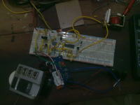
") wow great start button.. love it! upload some pics having better resolution. ;-)
wow great start button.. love it! upload some pics having better resolution. ;-)
adding a capacitor across the power supply to the ICs will make the change. a 220 - 470 uf will do.


sorry nidhin. i was out of station for a while.. now im back! happy to know that its working now