jayanth.devarayanadurga
Banned
- Joined
- Dec 4, 2012
- Messages
- 4,280
- Helped
- 822
- Reputation
- 1,654
- Reaction score
- 791
- Trophy points
- 1,393
- Location
- Bangalore, India
- Activity points
- 0
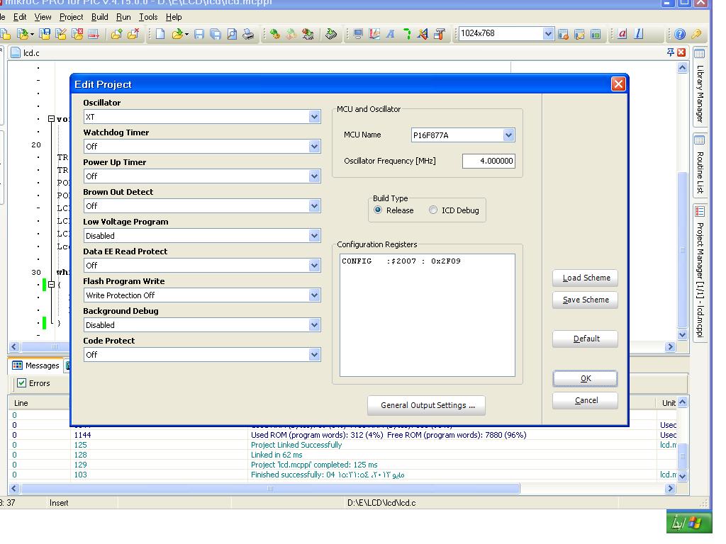
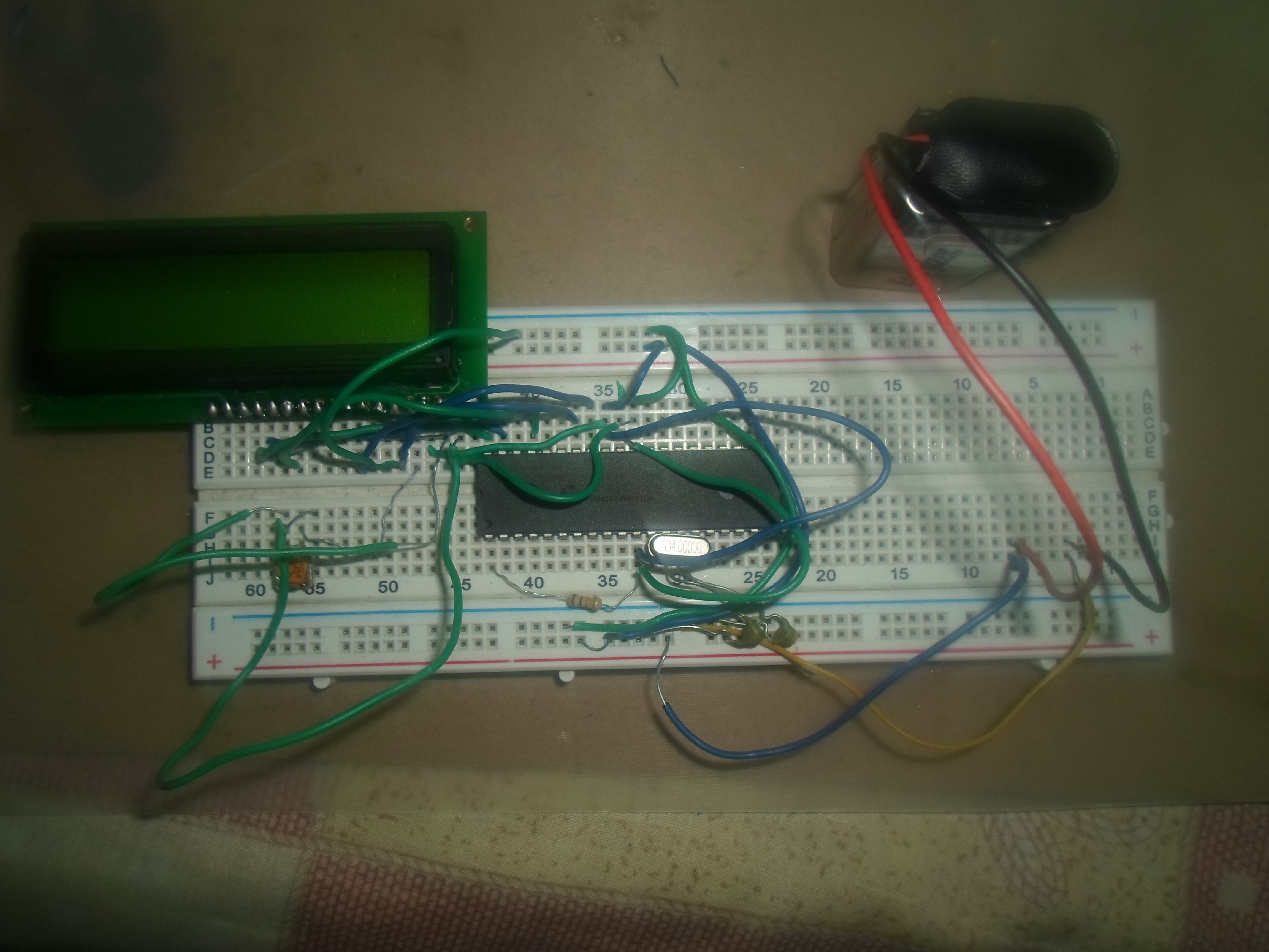
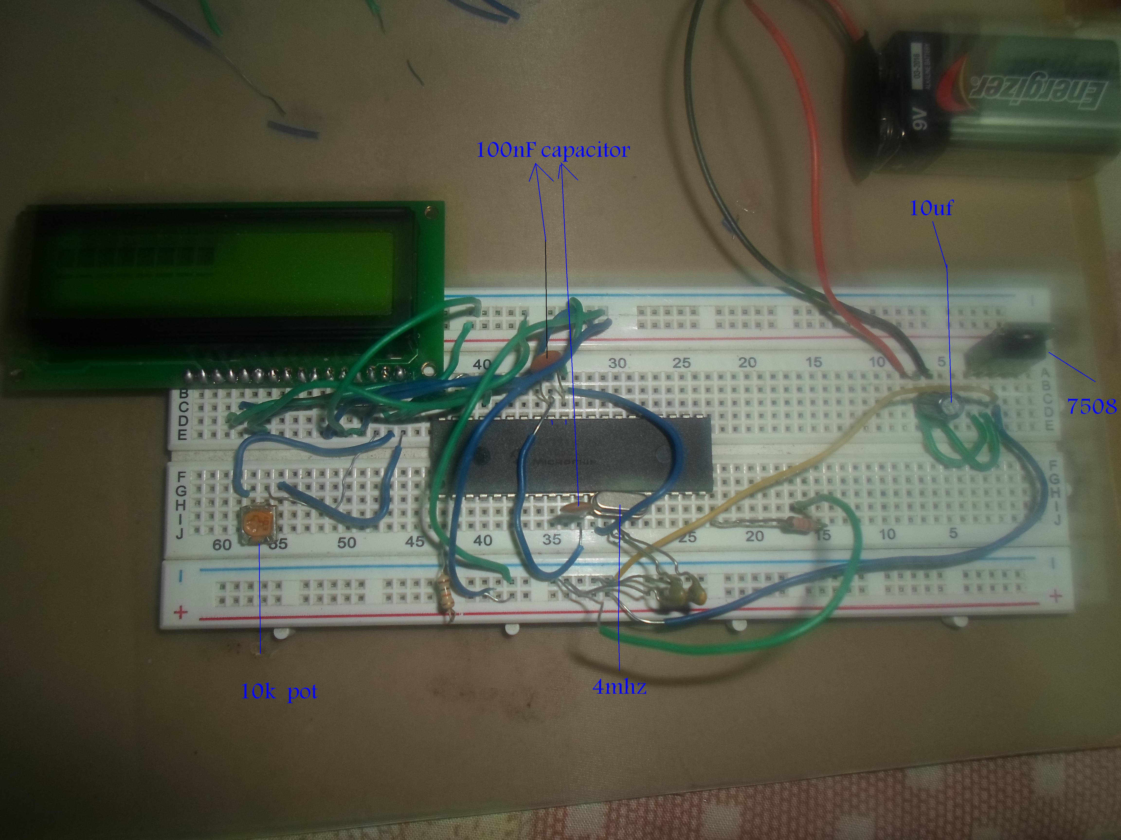
Did you Compile the code for PIC16F877A and 4 MHz. Zip and post your mikroC project files.