Continue to Site

Welcome to EDAboard.com

Welcome to our site! EDAboard.com is an international Electronics Discussion Forum focused on EDA software, circuits, schematics, books, theory, papers, asic, pld, 8051, DSP, Network, RF, Analog Design, PCB, Service Manuals... and a whole lot more! To participate you need to register. Registration is free. Click here to register now.

help my lcd project lmb16abd and 16f877a

Status
Not open for further replies.

hesho90

Member level 4
Member level 4
Joined
Sep 3, 2012
Messages
78
Helped
0
Reputation
0
Reaction score
0
Trophy points
1,286
Location
egypt
Visit site
Activity points
1,778
hello
i have lmb162abc lcd and pic 16f877a
and this is my code
sbit LCD_RS at RB0_bit;
sbit LCD_EN at RB1_bit;
sbit LCD_D4 at RB4_bit;
sbit LCD_D5 at RB5_bit;
sbit LCD_D6 at RB6_bit;
sbit LCD_D7 at RB7_bit;

sbit LCD_RS_Direction at TRISB0_bit;
sbit LCD_EN_Direction at TRISB1_bit;
sbit LCD_D4_Direction at TRISB4_bit;
sbit LCD_D5_Direction at TRISB5_bit;
sbit LCD_D6_Direction at TRISB6_bit;
sbit LCD_D7_Direction at TRISB7_bit;


void main() {


LCD_init();
Lcd_Out(1, 1, "hello");

}

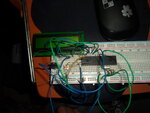
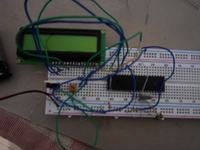
this i but the code on the pic and use my breadboard to see it but nothing is there
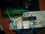
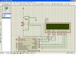
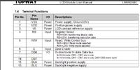
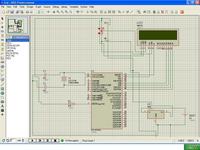
SAM_1917.JPGSAM_1918.JPGSAM_1919.JPGthe proteus.JPG

5v reg
 

Did the Proteus simulation work?


Try after connecting D0, D1, D2, D3 to ground... adjust the contrast of the LCD by varying the pot..or preset.

i wired all the d1-4 to ground


this is my new code
sbit LCD_RS at RB0_bit;
sbit LCD_EN at RB1_bit;
sbit LCD_D4 at RB4_bit;
sbit LCD_D5 at RB5_bit;
sbit LCD_D6 at RB6_bit;
sbit LCD_D7 at RB7_bit;

sbit LCD_RS_Direction at TRISB0_bit;
sbit LCD_EN_Direction at TRISB1_bit;
sbit LCD_D4_Direction at TRISB4_bit;
sbit LCD_D5_Direction at TRISB5_bit;
sbit LCD_D6_Direction at TRISB6_bit;
sbit LCD_D7_Direction at TRISB7_bit;


void main() {

TRISB = 0;
LCD_init();
Lcd_Out(1, 1, "hello");
}

and still nothing and the regulator very hot very fast
and i need help to know my ground from vdd in the pot
 

What is the value of POT you used?
Check whether the VDD, VSS of PIC and LCD are correct ...
Connect the constant resistance points of POT to VDD and VSS, variable resistance point to Ve of LCD..
Check the link that I give you...
do i have to use the same code from the your link
 

some black dots are shown on the lcd

d7-rb7.d6-rb6.d5-rb5.d4-rb4.en-rb0.rs-rb1
vss-gnd-pot .vdd-pot-5v.rw-gnd.d1:4 nothing
v0-pot middle pin
lmb16 lmb16abd


Change

Code C - [expand]
1
2
sbit LCD_RS at RB0_bit;
sbit LCD_EN at RB1_bit;


to


Code C - [expand]
1
2
sbit LCD_RS at RB1_bit;
sbit LCD_EN at RB0_bit;

this my new code
sbit LCD_RS at RC0_bit;
sbit LCD_RW at RC1_bit;
sbit LCD_EN at RC2_bit;
sbit LCD_D0 at RB0_bit;
sbit LCD_D1 at RB1_bit;
sbit LCD_D2 at RB2_bit;
sbit LCD_D3 at RB3_bit;
sbit LCD_D4 at RB4_bit;
sbit LCD_D5 at RB5_bit;
sbit LCD_D6 at RB6_bit;
sbit LCD_D7 at RB7_bit;

sbit LCD_RS_Direction at TRISC0_bit;
sbit LCD_RW_Direction at TRISC1_bit;
sbit LCD_EN_Direction at TRISC2_bit;
sbit LCD_D0_Direction at TRISB0_bit;
sbit LCD_D1_Direction at TRISB1_bit;
sbit LCD_D2_Direction at TRISB2_bit;
sbit LCD_D3_Direction at TRISB3_bit;
sbit LCD_D4_Direction at TRISB4_bit;
sbit LCD_D5_Direction at TRISB5_bit;
sbit LCD_D6_Direction at TRISB6_bit;
sbit LCD_D7_Direction at TRISB7_bit;


void main() {
TRISC = 0;
TRISB = 0;
LCD_init();
Lcd_Out(1, 1, "hello");
}
 

fide? fade? Post your new code. Post your Circuit.

sbit LCD_EN at RB0_bit;
sbit LCD_RS at RB1_bit;
sbit LCD_D4 at RB4_bit;
sbit LCD_D5 at RB5_bit;
sbit LCD_D6 at RB6_bit;
sbit LCD_D7 at RB7_bit;

sbit LCD_EN_Direction at TRISB0_bit;
sbit LCD_RS_Direction at TRISB1_bit;
sbit LCD_D4_Direction at TRISB4_bit;
sbit LCD_D5_Direction at TRISB5_bit;
sbit LCD_D6_Direction at TRISB6_bit;
sbit LCD_D7_Direction at TRISB7_bit;


void main() {
TRISA = 0;
TRISB = 0;
LCD_init();
Lcd_Out(1, 1, "hello");
}


4mhz crystal and 10k pot and 5v regulator
 
Last edited:

The unused (D0-D3) pins of the LCD should be tied HIGH or left disconnected for 4-bit operation, not tied low as suggested earlier. I suspect the real problem here is the layout and lack of decoupling capacitors are causing the clock to act erraticly and the voltage regulator to oscillate. Connect a 10uF capacitor across the input pin and ground pin of the regulator and a 100nF caocaitor between the output pin and ground pin. Also connect another 100nF capacitor between the VSS and VDD pins of the PIC, as close to the pins as possible.

Brian.
 

i don't know how to wire them all at the same time when i give power to the lcd it cut off on the pic and the pic cut it off on everything
 

Status
Not open for further replies.

Similar threads

Part and Inventory Search

Welcome to EDABoard.com

Sponsor

Back
Top