Continue to Site

Welcome to EDAboard.com

Welcome to our site! EDAboard.com is an international Electronics Discussion Forum focused on EDA software, circuits, schematics, books, theory, papers, asic, pld, 8051, DSP, Network, RF, Analog Design, PCB, Service Manuals... and a whole lot more! To participate you need to register. Registration is free. Click here to register now.

Help me with ADC module of PIC16f877A microcontroller

Status
Not open for further replies.

electronics_guy

Member level 2
Joined
Apr 12, 2012
Messages
49
Helped
0
Reputation
0
Reaction score
0
Trophy points
1,286
Activity points
1,655
I have some doubt about PIC microcontroller. I want to know, is it possible to group the channels of ADC module in PIC micro controller, I mean, there are a total of 8 channels in ADC module, so can I group them, say 5 in one group to perform ADC and 3 in other group to perform some Sample and Hold circuit.... Is it possible to do it?


Thanks in advance.....
 

1 ADC channel in micro controller is used to measure analog input , you can use it to read any analog sensors ex. temperature , and use the other one to read analog voltage...So on
what do you mean by grouping ADC channel
 

The ADC in the Pic16f877 can only read one channel at a time.
You have to select the input channel, make the reading, select the next channel, etc.

If you need to sample more than one channel simultaneously, you need to move to the more powerful 16-bit micros, Pic30, Pic33, Pic24.
The ADC in these chips can convert up to four channels simultaneously.
 
Thank you very much btbass.... That helped.

---------- Post added at 11:35 ---------- Previous post was at 11:34 ----------

And also I was searching some example code and I came across one code where they have used 7u,2u etc. many a times in the code(C language). What does that mean, can anyone plz help?


Thanks in advance.
 

The 'u' informs the compiler that the number is an unsigned type.
You will see this a lot in code that is MISRA compliant.
The MISRA rules complain if you use mixed signed and unsigned arithmatic.

/* Assisgning a signed number to an unsigned variable */

unsigned char x = 4; /* MISRA complains */

unsigned char x = 4U; /* MISRA is happy */


Thanks a lot Tahmid! Your tutorials are really helpful! Thanks a lot! I have some doubts about the ADC of PIC16F877A. When we configure the pins of ADC(AN0-AN7) as either analog or digital by using the PCFG<3:0> bits, what exactly are we doing? I mean if i configure 4 pins to act as a digital and the rest to act as analog, does it mean that I can pass the analog input signal only to the pins configured as analog and not to the digital pins? or does it have some other meaning to it?! Kindly help me with this!

Thanks in advance
 

Yes, that's what it means. When you configure any pins as analogue, only those pins can act as input for analogue voltage/signal and thus for ADC. The ones configured for digital can only read if the input is high (1) or low (0).

Hope this helps.
Tahmid.
 
Yes, that's what it means. When you configure any pins as analogue, only those pins can act as input for analogue voltage/signal and thus for ADC. The ones configured for digital can only read if the input is high (1) or low (0).

Hope this helps.
Tahmid.

Thanks Tahmid. That helped. :)
 

Yes, that's what it means. When you configure any pins as analogue, only those pins can act as input for analogue voltage/signal and thus for ADC. The ones configured for digital can only read if the input is high (1) or low (0).

Hope this helps.
Tahmid.


Hi Tahmid,

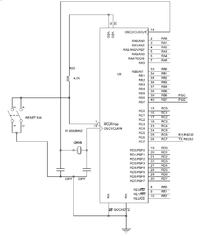
Your tutorials are really very good. Although you have very clearly mentioned every detail in your tutorials, I have some doubts. You have mentioned that we need to use decoupling capacitors If we do not use internal Vdd and Vss as Vref+ and Vref- and also you have given the values of these capacitors in your tutorials. But the schematic of the board I am using is slightly different than the one that you have uploaded. I have uploaded mine, kindly have a look at it and suggest me the capacitor that is to be used. This is really important. Kindly help.


Thanks


Connect one decoupling capacitor between pins 11 and 12 and another between pins 31 and 32.

If you intend to use external reference, you'll need to use pins 4 and 5 for VREF- and VREF+ respectively. So, you'll need to connect a decoupling capacitor across pins 4 and 5.

Hope this helps.
Tahmid.
 

Connect one decoupling capacitor between pins 11 and 12 and another between pins 31 and 32.

If you intend to use external reference, you'll need to use pins 4 and 5 for VREF- and VREF+ respectively. So, you'll need to connect a decoupling capacitor across pins 4 and 5.

Hope this helps.
Tahmid.

Thanks a lot Tahmid!
And what about the value of the capacitors to be connected?

Thanks
 

There isn't any strict requirement for the value. 100nF is okay.

Hope this helps.
Tahmid.
 

There isn't any strict requirement for the value. 100nF is okay.

Hope this helps.
Tahmid.


Thank u so much Tahmid! Thanks a ton! :)


But my question is, why do we need to use those capacitors if we intend to use external reference? What happens if I dont use?


Thanks
 

That capacitor is the bypass capacitor (also called decoupling capacitor): https://en.wikipedia.org/wiki/Decoupling_capacitor

Thanks Tahmid.
Just for understanding further, I just tried connecting external reference voltage at AN3 n AN2 but WITHOUT any decoupling capacitors, result was I always was getting a constant voltage of 3V, irrespective of supply voltage. Could you please explain me this? This is just to get a further idea.


Thanks a lot
 

Without a decoupling capacitor, you may not face a problem most of the times. And probably you will not. But having it will ensure that noise does not affect it.

Hope this helps.
Tahmid.
 

Without a decoupling capacitor, you may not face a problem most of the times. And probably you will not. But having it will ensure that noise does not affect it.

Hope this helps.
Tahmid.


Thank you very much
 

Without a decoupling capacitor, you may not face a problem most of the times. And probably you will not. But having it will ensure that noise does not affect it.

Hope this helps.
Tahmid.


Hi Tahmid,

I connected the capacitors as told by you, but there is a problem though. I connected a 0.01uF capacitor across AN3 and AN2 since I wanted to use external reference voltage. However when I turned on the power supply, a voltage of 3V and I could not change it at all! It was constantly displayed even though I had kept both voltage and current to minimum and the voltage did not change even when I tried changing it! It always always at 3V. When I disconnected the power supply from the PIC Board, I could vary the voltage. So I guess some reverse current is flowing from the board. Am I right?
If not, what could be the probable solution?
Kindly help.


Thanks
 

Without a decoupling capacitor, you may not face a problem most of the times. And probably you will not. But having it will ensure that noise does not affect it.

Hope this helps.
Tahmid.


Thanks Tahmid. I was finally able to resolve the problem.
But I have another question: In your blog "Modalities Of Using The ADC Module" you have mentioned about a Voltage Divider circuit which is to be used when we want to measure voltages greater than 5.5V. So what are the resistor values to be used i.e the values of R1 and R2? I intend to measure voltage up to 12V, please help me with this.


Thanks in advance
 

Status
Not open for further replies.

Similar threads

Part and Inventory Search

Welcome to EDABoard.com

Sponsor

Back
Top