Continue to Site

Welcome to EDAboard.com

Welcome to our site! EDAboard.com is an international Electronics Discussion Forum focused on EDA software, circuits, schematics, books, theory, papers, asic, pld, 8051, DSP, Network, RF, Analog Design, PCB, Service Manuals... and a whole lot more! To participate you need to register. Registration is free. Click here to register now.

help me to power my pic16f877a

Status
Not open for further replies.

aldawan

Newbie level 3
Joined
Oct 10, 2011
Messages
4
Helped
0
Reputation
0
Reaction score
0
Trophy points
1,281
Activity points
1,308
hi am new members and i new in micro controller
i have a pic16f877a and i want to power it
what should i do??
connect its pin 11 and 12 to 5v and ground only or connect pins 32 and 31 too >
thanks
 

Straight from the horse's mouth:

Many PICmicro MCUs have more than one VSS or VDD pin. This is common on
devices with higher pin counts. These pins are generally connected internally but
through a finite impedance. To insure proper operation, all VSS and VDD pins need
to be properly connected externally.

Microchip Power Considerations

BigDog
 

thanks for reply . i wanna ask a q?
i have 20*4 lcd and i want to power it
it a 16 pins VSS, VDD,VEE,RS RW , E , and from D0 to D7 data line and oins 15 and 16 should i connect all thi pins or what
 

VSS -> GND
VDD -> +5v
VEE -> connected to the middle pin of a 3 pin variable resistor... like this: 1st pin +5V... 2nd pin LCD-VEE... 3rd pin GND
RS, RW, E -> the connection depends on your design, per example, with an Arduino, i connect RS and E to Arduino, and RW to GND
D0 to D7 -> again, it depends on your design, you can use 8bit connection or 4bit connection, 4 bit is the most common and you use less pins
15 Led+ -> you can put a 330 ohm resistor in +5v to switch on the light of your LCD
16 Led- -> GND
 

hi could you draw to me the right connection in 4 bit to connect pic16f877a to 20*4 lcd
 

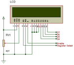
Here is a basic schematic for the LCD display

lcd.png

The R/W pin is hardwired to GND in the schematic (write only operation) but this depends on the library implementation , you may connect it to the mcu.

Alex
 

hi could any one draw to me a flow chart for this code

#include <16f877a.h>
#use delay(clock=20M)
#include <lcd420.c>
#include <LCD_D.h>
#fuses hs,nowdt,nocpd,nolvp,noprotect

#byte portc=0x07
#bit led=portc.4

void LCD_D();

unsigned int16 value;

void main()
{
set_tris_c(0x00);
led=1;
delay_ms(500);
LCD_D();
delay_ms(50);

while(1)
{
set_timer1(0);
setup_timer_1(t1_external | T1_DIV_BY_1);

delay_ms(1000); // in protues, should be 1000/3

setup_timer_1(T1_DISABLED);
value=get_timer1();
lcd_gotoxy(11,2);
printf(lcd_putc,"%LU HZ ",value);
led=!led;
}
}
 

Status
Not open for further replies.

Similar threads

Part and Inventory Search

Welcome to EDABoard.com

Sponsor

Back
Top