hbaocr
Full Member level 4
lpc2148 adc example
I have just studied ARM7 and using LPC2148. I have met some problems
about it. That I have done following the direction about ADC cell on
user menu LPC214x for writing keil C code base on example on site
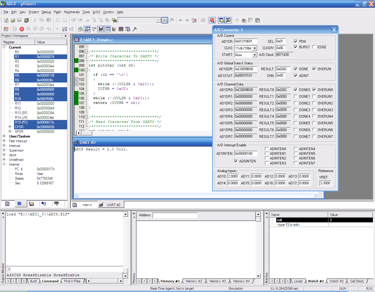
keilC.but it doesn't do as I want. The result of conversation alway
zero.Why it is? the result only display on AD1GDR but the result of it on its reg AD1DDR0 alway 0. why ?????
plZ send me some C code to solve that problem.
here my code
and project
I have just studied ARM7 and using LPC2148. I have met some problems
about it. That I have done following the direction about ADC cell on
user menu LPC214x for writing keil C code base on example on site
keilC.but it doesn't do as I want. The result of conversation alway
zero.Why it is? the result only display on AD1GDR but the result of it on its reg AD1DDR0 alway 0. why ?????
plZ send me some C code to solve that problem.
here my code
and project
Code:
/****************************************************/
/* Examples Program For "CP-JR ARM7 USB-LPC2148"    */
/* Target MCU  : Philips ARM7-LPC2148               */
/*       	   : X-TAL : 12.00 MHz                  */
/*             : Run Speed 60.00 MHz (With PLL)     */
/*             : PLL Setup = M(5),P(2)				*/
/*             : VPB Clock = CPU Clock = 60.00 MHz	*/
/* Keil Editor : uVision3 V3.03a                    */
/* Compiler    : Keil CARM V2.50a		            */
/* Create By   : Eakachai Makarn ([url]WWW.ETT.CO.TH[/url])    */
/* Last Update : 17/May/2006                        */
/* Function    : Example Display ADC8(P0.6)-> UART0 */
/****************************************************/
// Used GPIO0.6 = AIN8 (ADC8) Measure Voltage
// Display Result on UART0(9600,N,8,1)

#include "LPC214x.H" 	                                	// LPC2148 MPU Register
#include <stdio.h>											// For Used Function printf

/* pototype  section */
void init_serial0 (void); 									// Initil UART-0
int putchar (int ch);  										// Put Char to UART-0
int getchar (void);  										// Get Char From Uart-0
void delay(unsigned long int);								// Delay Time Function


unsigned int val;		   									// ADC Result (HEX)
float volt;													// ADC Result Volt

int main(void)
{
PCONP|=1<<20;//set PDA1
  init_serial0();				   							// Initial UART0 = 9600,N,8,1
   //Initial ADC8 (GPIO-0.6) By Set PINSEL0[13:12=11]
  // xxxx xxxx xxxx xxxx xx11 xxxx xxxx xxxx
  PINSEL0 |= 0x00003000; 									// Select ADC8 Pin Connect P0.6

  // Initial ADC8 (ADCR=0x01210601)
  AD1CR &= 0x00000000;										// Clear All Bit Control
  AD1CR |= 0x00000001;										// Select ADC = AIN8
  AD1CR |= 0x00000600;										// ADC Clock = VBP(PCLK) / 7
  AD1CR |= 0x00010000;                                      // Busrt = 1 = Conversion Continue
  AD1CR &= 0xFFF1FFFF;										// CLKS = 000 = 10Bit : 11 Cycle Clock Conversion
  AD1CR |= 0x00200000;										// PDN = 1 = Active ADC Module
  AD1CR &= 0xFF3FFFFF;										// TEST[1:0] = 00 = Normal Mode
  AD1CR &= 0xF7FFFFFF;										// EDGE = 0 = Conversion on Falling Edge
  AD1CR |= 0x01000000;										// START = 001 = Start Conversion Now

  // Start Test Read ADC8 and Display on UART0 //
  while(1)													// Loop Continue
  {
    do			  											// Loop Read ADC1.1(ADC8)
    {
      val = AD1DR0;                   						// Read A/D Data Register
    }
      while ((val & 0x80000000) == 0);  					// Wait ADC Conversion Complete	 .error
	  														//loop forever at this row on simulitor
	  val = (val >> 6) & 0x03FF; 							// Shift ADC Result to Integer
	  volt = val * 3.3 / 1023.0;	  						// Volt = ADC Result x [3.3V / 1024]
	  printf("\rADC8 Result = %1.1f Volt.",volt); 			// Display 3-Digit Result(0-3.3V)
	  delay(10000);
    }
}

/******************************/
/* Initial UART0 = 9600,N,8,1 */
/* VPB(pclk) = 60.00 MHz      */
/******************************/
void init_serial0 (void)
{
  PINSEL0 &= 0xFFFFFFF0;									// Reset P0.0,P0.1 Pin Config
  PINSEL0 |= 0x00000001;									// Select P0.0 = TxD(UART0)
  PINSEL0 |= 0x00000004;									// Select P0.1 = RxD(UART0)

  U0LCR &= 0xFC;											// Reset Word Select(1:0)
  U0LCR |= 0x03;											// Data Bit = 8 Bit
  U0LCR &= 0xFB;											// Stop Bit = 1 Bit
  U0LCR &= 0xF7;											// Parity = Disable
  U0LCR &= 0xBF;											// Disable Break Control
  U0LCR |= 0x80;											// Enable Programming of Divisor Latches

  // U0DLM:U0DLL = 60.00 MHz / [16 x Baud]
  //             = 60.00 MHz / [16 x 9600]
  //             = 390.6 = 391 = 0187H
  U0DLM = 0x01;												// Program Divisor Latch(391) for 9600 Baud
  U0DLL = 0x87;

  U0LCR &= 0x7F;											// Disable Programming of Divisor Latches

  U0FCR |= 0x01;											// FIF0 Enable
  U0FCR |= 0x02;											// RX FIFO Reset
  U0FCR |= 0x04;											// TX FIFO Reset
  U0FCR &= 0x3F;
}

/****************************/
/* Write Character To UART0 */
/****************************/
int putchar (int ch)
{
  if (ch == '\n')
  {
    while (!(U0LSR & 0x20));  								// Wait TXD Buffer Empty
    U0THR = 0x0D;                          					// Write CR
  }
  while (!(U0LSR & 0x20));									// Wait TXD Buffer Empty
  return (U0THR = ch);										// Write Character
}

/*****************************/
/* Read Character From UART0 */
/*****************************/
int getchar (void)
{
  while (!(U0LSR & 0x01));									// Wait RXD Receive Data Ready
  return (U0RBR);											// Get Receice Data & Return
}

/***********************/
/* Delay Time Function */
/*    1-4294967296     */
/***********************/
void delay(unsigned long int count1)
{
  while(count1 > 0) {count1--;}								// Loop Decrease Counter
}