Continue to Site

Welcome to EDAboard.com

Welcome to our site! EDAboard.com is an international Electronics Discussion Forum focused on EDA software, circuits, schematics, books, theory, papers, asic, pld, 8051, DSP, Network, RF, Analog Design, PCB, Service Manuals... and a whole lot more! To participate you need to register. Registration is free. Click here to register now.

[help]How to design this BGR

Status
Not open for further replies.

bkat

Member level 2
Member level 2
Joined
Dec 4, 2003
Messages
48
Helped
1
Reputation
2
Reaction score
1
Trophy points
1,288
Activity points
329
50_1161790433.jpg


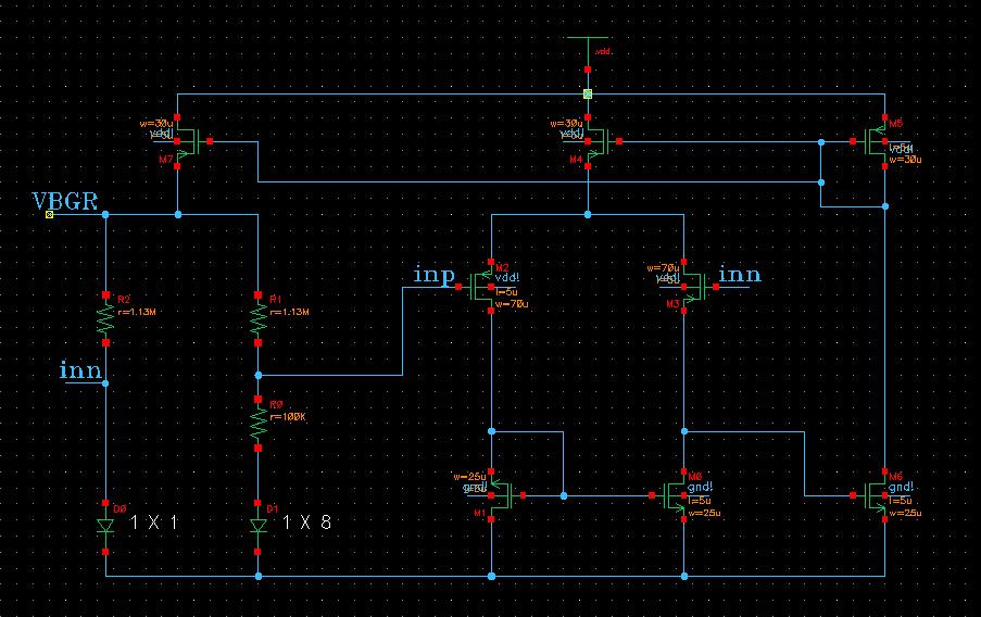
1 how to design this error amplifier?? (bandwith?? gain?? offset?? noise?? )

2 how to simulate the error amplifier independently??

3 how to simulate the PSRR of this BGR?


Thx

Regards

bkat
 

The amplifier should have a fairly large gain. Since the bandgap reference is mainly dealing with DC voltages the bandwidth doesn't need to be large. I would suspect it would need to have fairly low noise as well.

To simulate PSRR apply an AC signal to Vdd and measure the output of the BGR.
 

Where did you find this circuit? Could you provide the reference for this circuit? Thanks.

bkat said:
1 how to design this error amplifier?? (bandwith?? gain?? offset?? noise?? )

2 how to simulate the error amplifier independently??

3 how to simulate the PSRR of this BGR?


Thx

Regards

bkat
 

bkat said:
50_1161790433.jpg


1 how to design this error amplifier?? (bandwith?? gain?? offset?? noise?? )

2 how to simulate the error amplifier independently??

3 how to simulate the PSRR of this BGR?


Thx

Regards

bkat

1. The error amp used here should be high gain & low bandwidth. To lower the offset, you should use large W and L on differential pair. The current for err amp can be small.

2. Use Middlebrook's method to break the loop may be help. ( Use large L to break the loop and use large C to inject AC signal )

3. Apply AC signal to VDD and measure VBG.

Several memory papers use this topology to generate voltage reference. I myself consider it as a modification of Kuijk's BGR. It has the advantage of Kuijk's BGR ( No current mirror mismatch problem ), but lack of some disadvantage of Kuijk's BGR. Besides, the PSRR of the circuit should be better than Kuijk's.

Added after 1 hours 3 minutes:

isaacnewton said:
Where did you find this circuit? Could you provide the reference for this circuit? Thanks.

You can found similar topology in the attachment. The author refer back to P. Gray's and P.E. Allen's analog books ( old edition ). However, I cannot find it in P.E. Allen's book.
 
Last edited by a moderator:

I am a bit puzzled by this BGR circuit.

It appears the "start-up circuit" is missing, and the resisters are going to take a decent amount of real estate.

Is there any particular advantage to this design?
 

It looks like some PMOS and NMOS transistors are misused.
bkat said:
50_1161790433.jpg


1 how to design this error amplifier?? (bandwith?? gain?? offset?? noise?? )

2 how to simulate the error amplifier independently??

3 how to simulate the PSRR of this BGR?


Thx

Regards

bkat
 
Last edited by a moderator:

isaacnewton said:
It looks like some PMOS and NMOS transistors are misused.

i don't think so, just transistor draw direction lead mis-understanding
 

thanks ycj mince


Can you told me why error amplifier should be high gain and low bandwidth.

And in my opinion this amplifier's gain is about 50db .

Can you give me some advice no how to improve this BGR?

Regard

THX
 

1) the second stage of the amp is diode-connected load. it will decrease your gain. i guess the overall gain is around ~30dB?!

2) high bandwidth amp can give you better supply noise rejection in Mhz frequency range. high dc gain can give you a good bandgap voltage independent of PVT.
 

szekit said:
1) the second stage of the amp is diode-connected load. it will decrease your gain. i guess the overall gain is around ~30dB?!

2) high bandwidth amp can give you better supply noise rejection in Mhz frequency range. high dc gain can give you a good bandgap voltage independent of PVT.

to szekit

Thanks you for hlep.

off course the diode-connected will decrease the gain.but the diode-connected make the bias current of the opamp independent of PVT

Do you have any advice about the error amplifier?

thanks
 

no need the start up circuit

and the voltage range : 2v ~ 6v

bkat
 

devices process, voltage (supply) and temperature
 

bkat said:
thanks ycj mince


Can you told me why error amplifier should be high gain and low bandwidth.

And in my opinion this amplifier's gain is about 50db .

Can you give me some advice no how to improve this BGR?

Regard

THX

Error amplifier should be high gain, and you can trade bandwidth off. I don't think it hurts to have a high gain/high bandwidth err amp.
 

bkat said:
but the diode-connected make the bias current of the opamp independent of PVT

thanks

Independent of PVT?????

Diode connected current≈2*BJT current.
Though BGOUT has ~ZERO temp. coefficient, BJT current=ΔVd/R0 will have +ve temp. coefficient.

And the current will be process independent only if 'R0, R1, R2' are process independent; which won't be the case unless 'R's are external resistors. An onchip resistor will vary as much as 25% across process. So does the current.

point me if i am wrong.

Added after 4 minutes:

bkat said:
no need the start up circuit

bkat

Did you ramp the VDD and check?

Regards
 

ipsc said:
bkat said:
but the diode-connected make the bias current of the opamp independent of PVT

thanks

Independent of PVT?????

Diode connected current≈2*BJT current.
Though BGOUT has ~ZERO temp. coefficient, BJT current=ΔVd/R0 will have +ve temp. coefficient.

And the current will be process independent only if 'R0, R1, R2' are process independent; which won't be the case unless 'R's are external resistors. An onchip resistor will vary as much as 25% across process. So does the current.

point me if i am wrong.

Added after 4 minutes:

bkat said:
no need the start up circuit

bkat

Did you ramp the VDD and check?

Regards


Sorry !

You are right, is my mistake

Thank you !

Added after 1 minutes:

ipsc said:
bkat said:
but the diode-connected make the bias current of the opamp independent of PVT

thanks

Independent of PVT?????

Diode connected current≈2*BJT current.
Though BGOUT has ~ZERO temp. coefficient, BJT current=ΔVd/R0 will have +ve temp. coefficient.

And the current will be process independent only if 'R0, R1, R2' are process independent; which won't be the case unless 'R's are external resistors. An onchip resistor will vary as much as 25% across process. So does the current.

point me if i am wrong.

Added after 4 minutes:

bkat said:
no need the start up circuit

bkat

Did you ramp the VDD and check?

Regards


Sorry !

You are right, is my mistake.

the current Independent of PV.

Thank you !
 

bkat said:
off course the diode-connected will decrease the gain.but the diode-connected make the bias current of the opamp independent of PVT

thanks

two more question? thanks!

1. why this bandgap need not start-up circuit, i still see there are two stable work points.

2. as you see the opamp second stage diode connect transistor will decrease the opamp gain, then what is the merit of this configuration opamp to bandgap design.
 

All transistors could be in a off stage,
if there is no start-up circuit.

you might want to consider adding another transistor to your 2nd stage of the OPAMP.

What is PSRR spec, if VDD is between 2 and 6V?
 

then who can tell me the merit of the diode connection of the opamp second stage? thanks!
 

Status
Not open for further replies.

Part and Inventory Search

Welcome to EDABoard.com

Sponsor

Back
Top