Akeel Qadir
Newbie level 3

- Joined
- Sep 29, 2014
- Messages
- 4
- Helped
- 0
- Reputation
- 0
- Reaction score
- 0
- Trophy points
- 1
- Activity points
- 28
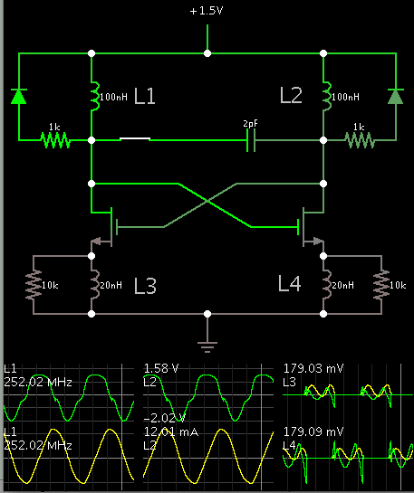
[Moved] how this circuit works ? can any body explains?
hi guys....

can anybody help me how this circuit works????
i need detailed working of this oscillator ??? please help
hi guys....
can anybody help me how this circuit works????
i need detailed working of this oscillator ??? please help