Continue to Site
Follow along with the video below to see how to install our site as a web app on your home screen.
Note: This feature may not be available in some browsers.
H bridge as in how? what did you intend to drive,where is the bootstrap circute ?
wait are you driven direct from the Ic?
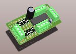
You're missing mounting holes (if you want them). It's a classic mistake ; )
") I have been debating whether to add them or not because that will increase the board size. Now since you mentioned it, I will figure out a way to add them. I think it's a good idea. Thanks for the feedback.
I have been debating whether to add them or not because that will increase the board size. Now since you mentioned it, I will figure out a way to add them. I think it's a good idea. Thanks for the feedback.The ground to the diodes of motors(D2,D4,D6,D8) should be GND-M instead of GND.
The ground should be a star ground as stated in the schematic. So it should not be connected else where. Also it is better to have a ferrite bead which can be mounted based on the need.Else a zero ohm resistor can be populated there.The ferrite bead suppress the noise coupled to GND as motor ground generally is too noisy.
You could look into vendor sites like
https://www.murata.com/products/emc/selection_guide/emc/index.html
ensure the footprint is compatible with a zero ohm resistor rated with 2A current.
I would recommend to contact the chip vendor as the internal plane details for the IC will be difficult to predict.