Continue to Site

Welcome to EDAboard.com

Welcome to our site! EDAboard.com is an international Electronics Discussion Forum focused on EDA software, circuits, schematics, books, theory, papers, asic, pld, 8051, DSP, Network, RF, Analog Design, PCB, Service Manuals... and a whole lot more! To participate you need to register. Registration is free. Click here to register now.

[SOLVED] Guitar Amplifier noise when a DC adaptor used.

Status
Not open for further replies.
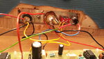
I have many switching power supplies that produce no hum. Yours produces hum because a main filter capacitor and/or rectifier diode is defective.
 

Hi,

I found calculating SMPS output LC filters to be hard/frustrating for certain reasons (input filters are far simpler to 'square circles' with), you might find it a breeze..., plus - if you don't know what's inside the 'black box' adapter, it might be a lot of trial and error to not cause adapter plug SMPS instability or just worsen the problem. I'm no expert.

You might want to look into just using an LDO/regulator at the entrance to your board for PSRR, place a simple <50hZ RC LPF between adapter and board, place an LC filter at the output, like a second-stage output filter, not sure if a common-mode choke would help here.
 

Attachments

  • 26to30.pdf
    58.3 KB · Views: 276

There are essentially two ways how hum can be injected to your circuit
- the adaptor doesn't produce clean DC but has some 100 Hz ripple superimposed
- an adaptor without earthing couples 50 Hz mains voltage to the floating circuit ground. Due to insufficient shielding of circuit, cable or guitar, the sensitive input picks up hum. A clear indicator for this problem would be that the hum reduces or even disappears when you unplug the guitar cable.

In the former case, the power supply needs additional filtering. In the latter case, try an additional earth connection of the circuit ground.

Hello. The amp still does hum when the guitar is unplugged. So, the problem is the power adapter. I have a cheap one and a fairly good one and both are humming. Can anybody tell me how to make a noise filter? I'm told that is very easy but I can't find any information on how to do it.
 

Hi,

Can anybody tell me how to make a noise filter? I'm told that is very easy but I can't find any information on how to do it.

:mad:

Really? Really...? I personally find that a bit offensive after the +30 minutes I spent looking for suitable information to help you and show different options. It's like you don't absorb the information people are providing you with, that or you don't bother to read the replies, or are just asking for another person to show you a picture/schematic of the components as you think it will be very difficult. I know it's exciting and overwhelming and stuff, but circuits are not exciting in that way or overwhelming, they are just cold-headed reading, doing some sums, then touching components and seeing something work (hopefully).

Re-read post #22, actually read it slowly and register what it says, follow the links provided in it and read the attached pdf, then you won't have to keep saying "I can't find any information on how to do it."

Read this, Passive Low Pass Filter, as well, it'll help. I promise you it is easy to work out an RC value for the input to your circuit a) with Ohm's Law not to reduce current too much you will need for the resistor, then b) calculate a capacitor value with this formula: 1/(2 x Pi x R x F) for the corner frequency you want. It will allow DC signals to pass, like the power supply voltage but block any AC signals (the noise) over whatever frequency in Hertz you choose. Basically, the noise you don't want will attenuate more and more as the frequency over the corner/cut-off frequency increases.

You might have 12 volts and need 1 amp for your circuit. 12 Volts/1 Amp = 12 Ohms. Let's choose a 10 Ohm resistor.

Now the capacitor value to filter out anything over... let's choose ~30Hz for overkill, we could choose 45 Hz just as well:

1/ (2 x 3.14 x 10 Ohms x 30Hz) = 1/1884 = 0.00053 Farads = 530uF. That's not a standard capacitor value, so we can use a very typical 470uF and the cutoff frequency is 33 Hz.

Hope it helps.

You should try FvM's repeated suggestion of earthing as he will presumably be very right in his analysis.
 

The main filter capacitor C24 is 1000uF and the bias filter capacitor C23 is 10uF and are already pretty good power supply filters when the circuit draws its normal fairly low current.

I notice on the schematic that only the poorly designed LM386 output stage and LED are turned off but the remainder of the circuit is still powered when the Power Switch is turned off. Then maybe the LM386 ICs have been overheated and now draw a huge power supply current that causes the hum. Do you have another amplifier that can be plugged into the SND jack to confirm?
 

Hi! no, I don't have another amp sadly. I don't know what the SND jack is ....
 

No, they don't get hot. I have the circuit grounded to an aluminium plate, but the input jack, the on/off switch, the LED and the dc jack are in another aluminium plate in the exterior of the box. I guess I should ground that plate too.
 

The Sleeve terminal of the input jack connects to the threaded part and nut that holds it to its metal plate. Of course it must be connected to the circuit ground.
 
Hi,


:mad:

Really? Really...? I personally find that a bit offensive after the +30 minutes I spent looking for suitable information to help you and show different options. It's like you don't absorb the information people are providing you with, that or you don't bother to read the replies, or are just asking for another person to show you a picture/schematic of the components as you think it will be very difficult. I know it's exciting and overwhelming and stuff, but circuits are not exciting in that way or overwhelming, they are just cold-headed reading, doing some sums, then touching components and seeing something work (hopefully).

Re-read post #22, actually read it slowly and register what it says, follow the links provided in it and read the attached pdf, then you won't have to keep saying "I can't find any information on how to do it."

Read this, Passive Low Pass Filter, as well, it'll help. I promise you it is easy to work out an RC value for the input to your circuit a) with Ohm's Law not to reduce current too much you will need for the resistor, then b) calculate a capacitor value with this formula: 1/(2 x Pi x R x F) for the corner frequency you want. It will allow DC signals to pass, like the power supply voltage but block any AC signals (the noise) over whatever frequency in Hertz you choose. Basically, the noise you don't want will attenuate more and more as the frequency over the corner/cut-off frequency increases.

You might have 12 volts and need 1 amp for your circuit. 12 Volts/1 Amp = 12 Ohms. Let's choose a 10 Ohm resistor.

Now the capacitor value to filter out anything over... let's choose ~30Hz for overkill, we could choose 45 Hz just as well:

1/ (2 x 3.14 x 10 Ohms x 30Hz) = 1/1884 = 0.00053 Farads = 530uF. That's not a standard capacitor value, so we can use a very typical 470uF and the cutoff frequency is 33 Hz.

Hope it helps.

You should try FvM's repeated suggestion of earthing as he will presumably be very right in his analysis.


I'm sorry if I offend anyone. As I told before, I'm REALLY new a this, I still don't know how the components work, nor to read the schemantics, nothing. Thats on my obviously, I'm looking for an electronic course in the mean time, I try to inform myself, but the more I see the more confusing it gets. I know you guys are trying to help and I appreciate it very much, but you have to understand that each user makes a different observation, some non related to the question, or the answers are too advanced for me to understand. Again, thats on me, I should have realize that this forum is for people who have advanced knowledge in the field. I do not pretend for you guys to give everything in a silver plater, and I'm sorry for that. I will read all the information that you provide again, It will took me forever, but I guess eventually I'll get there. Sorry.
 
On another thread, a new person to electronics described his HUM noise sounds like a swarm of mosquitoes, instead of a low frequency. What does your hum sound like?
 

On another thread, a new person to electronics described his HUM noise sounds like a swarm of mosquitoes, instead of a low frequency. What does your hum sound like?

That another new person is me! You guys must be hating me by now haha. Ok, I didn't use the terms correctly, so I'll pots a video of the amp and a clip from the phone mic so you can get the idea of what the sound is. By "a swarm of mosquitoes" I was talking about more the effect that the hum does when you turn down the pot "BBBZBZZZZZZ" than the frequency. In the mp4 attached, you'll hear the mic on 10, and then with the pot to 0 (I wire the capactiro to make it a low pass filter) and there is the humming.

AMP: Note how the bass potentiometer buzzez loudly when is turn to 0. I've builded 3 of these amps. 1st one gave it to a friend, didn't use the DC adaptor, just the 9V battery, the 2nd one didn't work out, and this one. On ALL OF THEM I had the same problem with the bass pot.
 

Attachments

  • 20201026_161143.mp4
    125.3 MB
  • amp.jpg
    amp.jpg
    587.7 KB · Views: 76
  • tel mic.mp4
    1.1 MB
Last edited:

Your hum is caused by the long unshielded wires (antennas for hum pickup) between the pots and the circuit board. The circuit board is designed to have the pots mounted directly on it with no wires.

If the broken red plug is the input from the guitar then it might have a broken shield wire or the hum is picked up by the unshielded long wire between the jack for the red plug and the circuit board input. The metal plate holding the jack for the red plug might not be grounded to the circuit board.
I cannot see if the TIP and Sleeve terminals of the jack are connected swapped.
 

Hello. The amp still does hum when the guitar is unplugged. So, the problem is the power adapter.
The conclusion is only correct, if the amplifier itself is shielded in a metal box. Is it?
 

The conclusion is only correct, if the amplifier itself is shielded in a metal box. Is it?


It is not in a metal box, I haven't manage to get one to fit the pcb, its very large! so I put it in a aluminium plate, put I guess that it needs to be inside a metal box without exceptions.
 

Metal plate isn't bad, of course it must be connected to circuit ground. Moving your hand above the circuit shouldn't change the hum intensity.
 

Hi,

plase upload a photo of the amplifier with all your wiring.
I´d like to see where the wire go to.

And please post a photo of the solder side of the amplifier. Here i´d like to see the traces of the PCB.

Klaus
 

Hi,

plase upload a photo of the amplifier with all your wiring.
I´d like to see where the wire go to.

And please post a photo of the solder side of the amplifier. Here i´d like to see the traces of the PCB.

Klaus

I'll attach them. The solder site is from another amp that didin't go well, but its the same PCB
 

Attachments

  • 20201026_204833.jpg
    20201026_204833.jpg
    1.1 MB · Views: 98
  • 20201026_204843.jpg
    20201026_204843.jpg
    1.1 MB · Views: 95
  • 20201026_204911.jpg
    20201026_204911.jpg
    3.6 MB · Views: 97
  • 20201026_204917.jpg
    20201026_204917.jpg
    3.7 MB · Views: 90
  • 20201026_205356.jpg
    20201026_205356.jpg
    3.4 MB · Views: 95

Hi,

To reduce noise:
There are at least 5 GND connections on/to the PCB. Please use only one PCB GND connection and connect here all periferal GNDs with extra wires..in star point manner.
Additionally connect the cases of the pots to the star GND.

Klaus
 
Status
Not open for further replies.

Similar threads

Part and Inventory Search

Welcome to EDABoard.com

Sponsor

Back
Top