Continue to Site

Welcome to EDAboard.com

Welcome to our site! EDAboard.com is an international Electronics Discussion Forum focused on EDA software, circuits, schematics, books, theory, papers, asic, pld, 8051, DSP, Network, RF, Analog Design, PCB, Service Manuals... and a whole lot more! To participate you need to register. Registration is free. Click here to register now.

GSM/Gprs Modem power supply

Status
Not open for further replies.

raja_merit

Newbie level 5
Joined
Jun 27, 2009
Messages
8
Helped
0
Reputation
0
Reaction score
0
Trophy points
1,281
Location
India
Activity points
1,339
sim548 svhematic

HI,
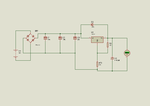
i am designing a gsm/gprs modem using sim 300 module. i m going to design power supply using 7805 regulator to get 5 v supply and to use 2n3055,current boosting amplifier at the end to withstand the load upto 2A.... is it ok to use this or can i use any other method
 

modem power supply

If your power supply delivers 2A, You can use the same. Or for compactness you may use 5volt 2A smps.
 

what power supply do they use in india?

Hi,
Better use switching regulator. Using linear regulator and then amplify current with transistor is an inefficient method. I can help you in this regard if you spell out about the voltage of your input source. Thanks.
 

power supply gsm module ldo

Search this forum - power supply design for SIM300 has been addressed several times. You need a PS that has good load regulation and transient response. An LM317T with a well filtered input and output works well.
 
gsm power supply

if you use lm7805 u are going to spoil the sim300 module coz its rated for 4.2V max so make a simple powersupply using lm317t and use a 10k adjustable preset for varying the voltage and a 220 ohm resistor between vout and adj pins just add a good 1000uF electrolytic capacitors at the output preferrably 2nos in parallel and add a 100nF ceramic capacitor to filter the noise. use a standard LG FWT adaptor SMPS type, rated for 9VDC and 1A thats enough and works well. but before connecting the sim300 module adjust the output voltage to 4.2VDC (max typical is 4V). do not exceed this voltge rating as you will damage the sim 300, this psu will work with all simcom modules - sim 300z, sim300c, sim300d, sim 548c, sim 548, sim 600 etc.
dont worry about the 2A rating given in datasheet coz when you add the 2X1000uF caps in parallel at o/p of your supply it will buffer enough current okay!

Added after 14 minutes:

here is the schematic for your convenience. ive been using this power supply with all my simcom designs, ive used it with sim300z,c,d,340e,548c,548z,600. if you want auto power on of the module you can connect a 470uF cap with its +ve connected to the pwrkey pin and -ve connected to ground and add a 100k resistor between vbat and pwrkey i.e. pull up.

Added after 56 seconds:


gprs modem capacitor

raghavendratalekar said:
if you use lm7805 u are going to spoil the sim300 module coz its rated for 4.2V max so make a simple powersupply using lm317t and use a 10k adjustable preset for varying the voltage and a 220 ohm resistor between vout and adj pins just add a good 1000uF electrolytic capacitors at the output preferrably 2nos in parallel and add a 100nF ceramic capacitor to filter the noise. use a standard LG FWT adaptor SMPS type, rated for 9VDC and 1A thats enough and works well. but before connecting the sim300 module adjust the output voltage to 4.2VDC (max typical is 4V). do not exceed this voltge rating as you will damage the sim 300, this psu will work with all simcom modules - sim 300z, sim300c, sim300d, sim 548c, sim 548, sim 600 etc.
dont worry about the 2A rating given in datasheet coz when you add the 2X1000uF caps in parallel at o/p of your supply it will buffer enough current okay!

Added after 14 minutes:

here is the schematic for your convenience. ive been using this power supply with all my simcom designs, ive used it with sim300z,c,d,340e,548c,548z,600. if you want auto power on of the module you can connect a 470uF cap with its +ve connected to the pwrkey pin and -ve connected to ground and add a 100k resistor between vbat and pwrkey i.e. pull up.

Added after 56 seconds:


i look at your schematic that Vin = 9 V, if i use 12 V adaptor or i use 12V accu, is the output can i get the range from 3,5V-4,5V just with adjust the potentiometer??
 

india sim300z

I use a simlar design on my power supplies, but I would recommend you use fixed resistors in place of the pot. There's no reason you should have to adjust the voltage and if the pot is accidently changed you run the risk of burning out the module.

Use 1% metal film resistors. Replace V1 with a 510 ohm resistor and you'll get an output of 4.15 volts. If you want a different output voltage, here's a link to a handy on-line calculator for determining the LM317 resistor values: https://www.muzique.com/schem/lm317.htm
input voltages.
 

gsm module 5v supply

GSM Man said:
I use a simlar design on my power supplies, but I would recommend you use fixed resistors in place of the pot. There's no reason you should have to adjust the voltage and if the pot is accidently changed you run the risk of burning out the module.

Use 1% metal film resistors. Replace V1 with a 510 ohm resistor and you'll get an output of 4.15 volts. If you want a different output voltage, here's a link to a handy on-line calculator for determining the LM317 resistor values: https://www.muzique.com/schem/lm317.htm
input voltages.

thx for explanation, i'll try it...
 

best gprs modems in usa

thats right using 1% resistors but buddy you would need at least 1w rating for that okay so go for a pot and dont forget to add the 100nF cap in parallel to the pot that will avoid anny ripples in Vadj. we have been in this sim300 business since long time and do manufacture modems which use the same design okay just visit **broken link removed**

Added after 2 minutes:

you can use even a 500mA rated adaptor for the input voltage but you will need atleast 6X1000uF tantalum caps at the output i.e. between VBAT & ground, this is how they do it for USB powered modems.
 

sim300 sim300z dif

raghavendratalekar said:
thats right using 1% resistors but buddy you would need at least 1w rating for that
What in the world are you talking about! You don't need a 1W resistor for the adjustment terminal, and if you did it wouldn't matter if it was a fixed reistor or pot!

You can put a cap on the adjustment terminal, but what's more important is the size of the caps on the input and output of the regulator. They need to be large enough to ensure that you have very low ripple under load.
 

connect sim300 pot connection

Hi all;)

I have one question:
Do you use to put heat sink for LM317T with 9VDC adaptor or there is no need?

Thanks in advance
 

6oo u gprs modem

Hi,
Better results for switching regulator with max current up to 2.5A and LiIon charger circuit with 400mA limited current output. The LDO regulators are for uc & gps module power supply. All resistors are 1% metal film. Thanks
 

for power supply use LM2576 IC.
 

Re: 6oo u gprs modem

jsidev said:
Hi,
Better results for switching regulator with max current up to 2.5A and LiIon charger circuit with 400mA limited current output. The LDO regulators are for uc & gps module power supply. All resistors are 1% metal film. Thanks

dear jsidev,
in your schematic, in the upper right corner, you have two power outputs: 1) +VCC uC and 2)+VCC AUX. The first one is connected to main power suply of uC. The second one what is for? Is it to power any other device you may have?

And another question,
in the buttom of your schematic you have a wire labeled "uC charge sw". This wire is connected directly to the uC or is there any other circuit you must to put?

Thank you in advance
:D:DΨ:D
 

Hi all.
I am trying to design a board for my sim508.
when i dont have any antenna current is 50mA and voltage with lm317t is 4 volt, and module work correctly .
but when i connect gsm antenna current after 10 second go to 160mA and voltage is 4volt , module dont work, in other words dont work "ATD6586..." or "AT+CIMI" give me error.
 

hy

So I just connected my SIM900 with 3x Tantalum electrolytic capacitor, SMD 470 uF 6 VDC (ESR 0.065 Ω)

But still I get a voltage drop of 840mV over a time of 1.2mS from 4V to 3.2V that's too much I think but what can I change?

Thx
Andy
 

hy

So I just connected my SIM900 with 3x Tantalum electrolytic capacitor, SMD 470 uF 6 VDC (ESR 0.065 Ω)

But still I get a voltage drop of 840mV over a time of 1.2mS from 4V to 3.2V that's too much I think but what can I change?

Thx
Andy

The capacitors are not enought to average-out the current (as incorrectly suggested on this forum).
You need a regulator that can supply the peak current and react quickly enough.
Alternatively you could use a good battery or very large caps (>>100milliF).
 

im trying to use this circuit for sim300 supply , is it OK ?
 

Attachments

  • Untitled.png
    Untitled.png
    127 KB · Views: 148

Status
Not open for further replies.

Similar threads

Part and Inventory Search

Welcome to EDABoard.com

Sponsor

Back
Top