Continue to Site

Welcome to EDAboard.com

Welcome to our site! EDAboard.com is an international Electronics Discussion Forum focused on EDA software, circuits, schematics, books, theory, papers, asic, pld, 8051, DSP, Network, RF, Analog Design, PCB, Service Manuals... and a whole lot more! To participate you need to register. Registration is free. Click here to register now.

Getting Started with NPN BJT Common Emitter Designing

Status
Not open for further replies.

Eshal

Advanced Member level 1
Joined
Aug 29, 2012
Messages
470
Helped
16
Reputation
32
Reaction score
15
Trophy points
1,298
Location
Nowhere :)
Visit site
Activity points
5,149
Hello experts!

I want to design my own common emitter circuit. I don't know what points should be remember as an electronics engineer for this designing.

I have this knowledge:
1) I have input voltage 10mVpp
2) I want output 10Vpp

Is this sufficient knowledge for the designing of the CE circuit? (i.e. calculating the values of R1, R2, RC and RE and also Vcc and values of bypass capacitors and values of coupling capacitors.)

Thank you all.
 

Before starting a detail calculation, you'll check if gain of 1000 is feasible with a single transistor stage. If you find that it isn't, you'll chose a different topology.
 
  • Like
Reactions: Eshal

    Eshal

    Points: 2
    Helpful Answer Positive Rating
Hi Eshal,
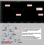
I simulated a transistor with a voltage gain as high as possible, an output of 10Vp-p and a 15V supply.
Its output is not clipping but is severely distorted.

I blacked-out its input signal level so that you must calculate its voltage gain.
 

Attachments

  • transistor without feedback.png
    transistor without feedback.png
    34.6 KB · Views: 163
  • Like
Reactions: Eshal

    Eshal

    Points: 2
    Helpful Answer Positive Rating
Hello experts!
I want to design my own common emitter circuit. I don't know what points should be remember as an electronics engineer for this designing.
I have this knowledge:
1) I have input voltage 10mVpp
2) I want output 10Vpp
Is this sufficient knowledge for the designing of the CE circuit? (i.e. calculating the values of R1, R2, RC and RE and also Vcc and values of bypass capacitors and values of coupling capacitors.)

Yes, in general, it is sufficient to specify a certain gain value - however, I suppose you have chosen an example value (1000) without knowing if this is feasible with one single stage or not.
As mentioned already, this value is too large. It will be even problematic to achieve a stable gain of 100. You should start choosing a suitable quiescent dc current Ic in the lower mA range.
 
  • Like
Reactions: Eshal

    Eshal

    Points: 2
    Helpful Answer Positive Rating
@FvM
Before starting a detail calculation, you'll check if gain of 1000 is feasible with a single transistor stage. If you find that it isn't, you'll chose a different topology.
You are right sir. CE amplifier can't give much gain and also Audioguru has proved it with his schematic too. It is severely distorted. What if I use Common Base because it provide such a high gain. Am I on the right track sir?

@crutschow
And why should I consider the frequency of the signal? By the here I am using the voice signal which has amplitude of the 10mVpp so its voice somewhere around 700Hz or more. Right?

@LvW
You are right. That's why I am trying with CB amplifier. Let see if I get my goal with it or not.


You are right sir. CE amplifier can't give much gain and also Audioguru has proved it with his schematic too. It is severely distorted. What if I use Common Base because it provide such a high gain. Am I on the right track sir?
.


You must discriminate between gain and maximum output voltage.
Distortions in Audiogurus simulation result from the supply voltage which is rather small in comparison to the required output amplitude.
Use a larger supply voltage (and some other resistor values) and the distortions will be lower.
You must clearly state what you want - and what your primary goal is.
Regarding common base: No - you are not on the right track. Common base provides the same gain as common emitter, but with a input resistance which is much smaller.
The only advantage is a higher bandwidth (not important in your case).
 
  • Like
Reactions: Eshal

    Eshal

    Points: 2
    Helpful Answer Positive Rating
@LvW
Are you sure Audioguru's used insufficient Vcc? Because my required is 10Vpp (5Vp and 5Vp) while Audioguru used 15Vpp (7.5Vp and 7.5Vp), my voltage's peak lies under 7.5Vp.

And yes I agree with you. So I should go with CE amplifier?

I just want to design an CE amplifier with nothing known. What I know is just I have input voltages 10mVpp and I want output 10Vpp. Just, I don't know what should be the Vcc (but I want to know how to calculate it during the designing), I don't know what should be values of Resistors (but I want to know how to calculate it during the designing), I don't know which Transistor should I use (but I want to know how to choose transistor for my this application) and I don't know what capacitors should I use (but I want to know formula which could calculate the values of the capacitors). It is all what I have and what I don't have.

Thank you all.
 

OK - so your only requirement is to have a gain of 1000, right?
It was in post#2 where FvM gave you the advice to recheck this requirement.
To achieve a gain of 1000 in one single BJT stage with "good" quality seems to be not possible.

All other questions regarding componenet values can be answered only after this gain conflict has been clarified.
Note that for good signal quality you need signal feedback, which in turn reduces the gain of the stage (Audioguru´s simulation has no signal feedback; hence, large distortions).
 
  • Like
Reactions: Eshal

    Eshal

    Points: 2
    Helpful Answer Positive Rating
OK - so your only requirement is to have a gain of 1000, right?
Yes, But see below quotations.
It was in post#2 where FvM gave you the advice to recheck this requirement.
To achieve a gain of 1000 in one single BJT stage with "good" quality seems to be not possible.
You are absolutely correct. We can't achieve our requirement with just single BJT stage. So let's reduce the output voltage requirement. Now I have input voltage same as before i.e. 10mVpp but my output is reduced to 3Vpp. This implies that the required gain is 300. Right?

All other questions regarding componenet values can be answered only after this gain conflict has been clarified.
I have cleared this point in above quote. Read it. I have changed my output voltages requirement to 3Vpp instead of 10Vpp.

Note that for good signal quality you need signal feedback, which in turn reduces the gain of the stage (Audioguru´s simulation has no signal feedback; hence, large distortions).
I know feedback reduces the gain of an amplifier. But for good signal quality we need feedback. How? I am listening this first time in my entire student life or perhaps I have heard but didn't pay any attention.
And by the way, should Audioguru connect a capacitor between collector and base of the Transistor, then you can say it has feedback. Huh??

Thanks again. Good points LvW
 

Only 1000 with single stage? not an easy task for a beginner

This requires extreme high impedance ratios on collector to emitter to generate enough current to keep it fairly constant then negative feedback to reduce the natural non-linear distortion which is a tradeoff with gain.

I choose a hFE or Beta of 100 and achieved a gain over 300 at 15V and almost 3000 at 100Vdc.

The loss is impedance ratio of output to input and power dissipation. A voltage source was used with 0 Ohm and 22k collector R. The negative feedback lowers input and output impedance. If the AC coupled load R matches the collector R then the signal drops 50% and is said to match the amplifier output impedance. It should never be lower than Rc, and of course gain x2 with a much higher impedance load.

Why does this work? Because Vc stays well away from the supply rail which implies big drop in Ic where gain becomes non-linear, and more important, it uses negative feedback to help self bias input based on output Vc and device characteristics.

It is a useful design, but not very good, as it consumes much more power than an multi-stage transistor design (such as an op amp) with more gain , regulated current mirrors with negative feedback controlling the gain. Here the voltage gain comes partly from current gain and partly from raising the impedance ratio from input to output. (ie opposite of a buffer)
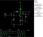
Here's a great Java EE simulation site for quick and dirty designs and my design for this forum.

I added a pot and variable supply so you can see how it can be improved when you raise the supply voltage and get a more constant collector current without expecting full swing. 1/3 swing is a good compromise as is a max gain of 200x per stage.

Notice also my poor design features of requiring very low emitter resistors with huge caps. Beware of RC time constants and low frequency response and start the simulator with full simulation speed slider to the right to settle the steady state.

CE amp.jpg Have Fun:cool:
I hope :thinker:
 
Last edited:

@SunnySkyguy
Sorry sir, your post is much related to professionals. I didn't understand what you have written at all. I am so sorry. But I understand you have did all for 1000 gain.

If you see post#10 and in that post I have mentioned that I want output now 3Vpp, not 10Vpp. So for 3Vpp the gain is only 300 required.
 

Are you sure Audioguru's used insufficient Vcc? Because my required is 10Vpp (5Vp and 5Vp) while Audioguru used 15Vpp (7.5Vp and 7.5Vp), my voltage's peak lies under 7.5Vp.

My output was 10Vp-p that you wanted. My supply voltage was 15VDC so it is plenty to make an audio amplifier with an output of ONLY 10Vp-p with EXTREMELY low distortion.
The problem with your transistor is that it is not an amplifier circuit, instead it is only a single transistor without a load.

I doubled the supply voltage in my circuit to 30V and changed the bias so that the output was half of the supply voltage but at 10Vp-p output there was less but still very high distortion. I did not try a 150V supply voltage which might work better. An ordinary audio amplifier has very low distortion even when its output level is almost clipping near the supply voltage rails. It has plenty of negative feedback.

I just want to design an CE amplifier with nothing known. What I know is just I have input voltages 10mVpp and I want output 10Vpp. Just, I don't know what should be the Vcc (but I want to know how to calculate it during the designing), I don't know what should be values of Resistors (but I want to know how to calculate it during the designing), I don't know which Transistor should I use (but I want to know how to choose transistor for my this application) and I don't know what capacitors should I use (but I want to know formula which could calculate the values of the capacitors). It is all what I have and what I don't have.
You do not have an amplifier with a gain of 1000. Instead you have a single transistor without a load and with a voltage gain of 200 with horrible distortion.

High gain needs two or three transistors and low distortion needs negative feedback. The negative feedback allows the amplifier circuit to have low distortion and a constant output level even when the load resistance changes.
 
Last edited:
  • Like
Reactions: Eshal

    Eshal

    Points: 2
    Helpful Answer Positive Rating
@Audioguru
Thank you for your reply. I understand the situation with 1000 gain. I have reduced my output voltages to 3Vpp. Now I want help. This can be achieve with a single transistor CE amplifier.
 

Eshal did you see my design with current gain of 100 and voltage gain from 300 to 3000?
I wonder if the Falstad simulator uses realistic transistor models? There are two parameters that limit achievable voltage gain of a transistor in common emitter (or common base9 configuration. No feedback like emitter degeneration presumed, of course.

1. gm = Ic/26mV for silicon transistors at ambient temperature. Because V = Rc*gm, the voltage can't can't be higher than V(Rc)/26 mV.
2. Output impedance respectively early voltage (SPICE parameter VAF). Rout = VAF/Ic
Usual Early voltage values of small signal transistors are in 50 to 100 V range.

In gain calculation, the Output impedance is connected in parallel to Rc.
 

@SunnySkyguy
Yes sir I saw it. And I understand what you have done but most of it I didn't get because we have never been taught in university in such depth. I don't know what parameters should I consider in designing this amplifier. I still on the starting of the track from where I started this thread.

- - - Updated - - -

@FvM
Sir, I have gain knowledge that for designing the simplest amplifier I need the following parameters at least;
1) Input voltages (in my case 10mVpp)
2) Output voltages (in my case 3Vpp)
3) DC voltage supply (for my case 10V is enough)

Can you guide me sir that with this information I can design the CE amplifier?
 

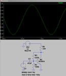
I tried SunnySkyguy's circuit in LTspice with a 2N3904 transistor and a 10V supply. With a very low impedance source, no emitter resistor and no load its output was almost 2.7Vp-p with an input of 10mVp-p.

The output swing is away from the positive supply and at a lower level than before so its distortion is reduced but is still noticeable.

R1 supplies negative DC feedback but the very low impedance of the signal source shorts any AC negative feedback from R1.
 

Attachments

  • transistor1.png
    transistor1.png
    17.8 KB · Views: 117
  • Like
Reactions: FvM

    FvM

    Points: 2
    Helpful Answer Positive Rating
Eshal, there are inherent limitations trying to achieve high gains (>100) with a single transistor. Is this for personal training?

For practical purposes, use an Operational Amplifier which has an open loop gain from a dozen or more transistors of more than a million which with negative feedback gain of 2 resistor ratios can easily achieve a gain of 300.
 

Status
Not open for further replies.

Part and Inventory Search

Welcome to EDABoard.com

Sponsor

Back
Top