Continue to Site

Welcome to EDAboard.com

Welcome to our site! EDAboard.com is an international Electronics Discussion Forum focused on EDA software, circuits, schematics, books, theory, papers, asic, pld, 8051, DSP, Network, RF, Analog Design, PCB, Service Manuals... and a whole lot more! To participate you need to register. Registration is free. Click here to register now.

Geiger counter using a boost converter 3V to 500V

Status
Not open for further replies.

strape81

Junior Member level 3
Joined
Dec 16, 2011
Messages
25
Helped
2
Reputation
4
Reaction score
2
Trophy points
1,283
Activity points
1,558
Hi everybody,

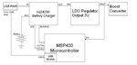
currently I am collecting information for designing a handheld Geiger counter using the tube ZP1401 von Centronic. The whole device will be supplied from a 3.7V rechargeable battery.The battery will be charged from a USB port. The basic components of this device will be a microcontroller that supports USB and a boost converter that will boost the 3V to 500V, the operating voltage of the tube. In the following block diagram you can see my concept.**broken link removed**

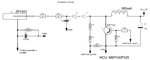
Searching a little bit in the market I have found the following circuit of a boost converter which is used in a well known geiger counter.
**broken link removed**

About this circuit there are some points that I would like to discuss with you...
1) Why is the voltage feedback path at the junction of the inductor and the power transistor and not at the output of the boost converter? Which is the advantage that I cannot clearly see???
2) As far as the feedback control technique concerns which could be the suitable one? Do you have any logical assumption for the current circuit? The input voltage is stable at 3V.I have taken into consideration two cases for output load: a) Itube=0A (ionisation absent) and b) Itube=500V/9M4=53.2uA (ionisation present).

Probably some things are still confused in my mind so new questions could arise from your answers!

Thanks a lot for your time!!!

Other datasheets: Sensor:View attachment ZP1401.pdf, MCU:View attachment msp430p325.pdf
 

**broken link removed**

**broken link removed**

Sorry, these both caused an error msg saying 'invalid attachment'.

1) Why is the voltage feedback path at the junction of the inductor and the power transistor and not at the output of the boost converter? Which is the advantage that I cannot clearly see???

The control section does not necessarily know what variations are the result of its adjustments, or due to something else.

For instance there may be some amount of ripple, etc.. The control section would go crazy as it tried to react quickly enough.

Nor can the control section know exactly what duty cycle to apply, since the output stage might contain a voltage multiplier, etc.

In any event, the control section must turn on the coil for a time, then turn it off for a time. It needs to detect a peak current in the coil so it can shut it off. Then it needs to detect a low, so it can turn it on again.

2) As far as the feedback control technique concerns which could be the suitable one? Do you have any logical assumption for the current circuit? The input voltage is stable at 3V.I have taken into consideration two cases for output load: a) Itube=0A (ionisation absent) and b) Itube=500V/9M4=53.2uA (ionisation present).

If you have not already added a voltage multiplier to the output stage, you might consider it. A tripler or greater.

It would let you run at a reduced duty cycle. The battery would not need to provide as high instantaneous current.
 

I send again the two pictures...my concept and the boost converter...thanks a lot for your answer BradtheRad!!!
 

Attachments

  • GeigerCounter_Concept.JPG
    GeigerCounter_Concept.JPG
    27.2 KB · Views: 195
  • powerstage.JPG
    powerstage.JPG
    65.5 KB · Views: 159

Your setup should work okay.

It should draw 22 mA at 3V. Duty cycle 88 percent.

Those figures are according to my simulation:


The 165 mH coil provides adequate step-up action. I was all wet about adding a voltage multiplier. It will not gain you anything.

Remember to make sure you connect the proper polarity to the center wire on the tube.

I seem to remember my geiger counter has a high resistance between the tube and the next stage. It reduces the risk of high voltage getting to low voltage components.
 
Hi BradtheRad!!!

As far as I understood from the inductor current waveform the boost converter should work in discontinuous mode if I want a manageable duty cycle. Till now I was simulating with 10-20kHz switching frequency and the duty cycle was 99.4%.
The picture compares the boost converter in CCM and DCM mode.

boost_ccm_dcm.JPG

DCM Mode
(+) Manageable duty cycle
(-) Bigger ferrite core

CCM Mode
(-) Duty Cycle
(+)Smaller ferrite core

Mmmm...tough decision! I will put both of them to the test and I will be back with reliable answers!
 

Yes, DCM is less desirable because you must make your coil capable of carrying higher current without saturating.

DCM causes stress to components due to sudden current switching (although 22 mA is not that much current).

CCM puts less stress on components. Switched-coil converters are often made to operate this way, a certain amount above and below the average current draw.

Your CCM is still in the typical range used in SMPS.

I suspect you could easily get by with a lower henry value than 165 mH. In any case the value is not critical.

Your coil will be a tradeoff between several factors. How much instantaneous current your supply can provide, how large you want the coil core to be, etc.

Also whether you like the idea of operating at an audible frequency. This is a case where it can be reassuring when you hear the supply whining.

Also remember that the volt level will start dropping more whenever the tube detects a large volume of radioactive particles. (The change in volt level on the tube causes the clicks we hear.) The volt level could need several cycles to recover, depending on how high it must be for the tube to work. Consider whether you want your supply to respond gradually or quickly.
 

Status
Not open for further replies.

Similar threads

Part and Inventory Search

Welcome to EDABoard.com

Sponsor

Back
Top