haxaan
Newbie level 2
I need help in completing my semester project on verilog. I have made the code and it is compiling well but when I try to simulate, I get dozens of errors. I will greatly appreciate if someone can guide me with this coz I need to transfer the code on Spartan-3 fpga very soon. Here is the complete code I have mustered by now:
//MAIN stimulus file
//PHASE ACCUMULATOR
//FOUR BIT ADDER
//PARABOLA GENERATOR
//TWO's COMLEMENT
//FULL ADDER TO BE USED IN TWO's COMPLEMENT
//MULTIPLIER
//FORMAT CONVERTER - FROM SIGNED TO UNSIGNED
Added after 3 hours 24 minutes:
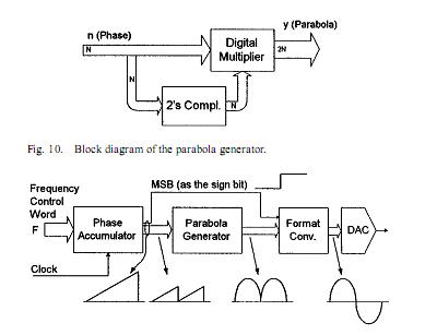
Block diagram of my project
//MAIN stimulus file
Code:
module main();
reg CLK;
	reg	signed [31:0] WORD;
	wire	[7:0] PARABOLA;
	wire [7:0]	PHASE;
	wire SIGN;
	wire [6:0] TEMP;
	//--------------

	accumulator_phase pa(.word(WORD), .clk(CLK), .phase(PHASE), .sign(SIGN));
	parabola_gen pg(.phase(PHASE), .parabola(TEMP));
	format_converter fc(.signed_parabola(TEMP), .sign_ac(SIGN), .out_bits(PARABOLA));

	initial // Clock generator
		begin
			CLK = 1'b0;
			WORD = 32'b0;
			WORD[13] = 32'sh01000000;

		end
	always
		begin
			#20 CLK = 1'b1;
			#20 CLK = 1'b0;
			#20 CLK = 1'b1;
			#20 CLK = 1'b0;
		end

	initial
		$monitor($stime, CLK, WORD, PARABOLA);

endmodule
//PHASE ACCUMULATOR
Code:
module accumulator_phase(word, clk, phase, sign);
    input [31:0] word;
    input clk;
    output [7:0] phase;
    output sign;
	 //------------
	wire signed [31:0] word;
	wire clk;
	wire c1, c2, c3, c4, c5, c6, c7, c8;
	reg signed [31:0] x;
	reg signed [31:0] res;
	reg [7 : 0] phase;
	reg sign;
	//-------

	//------------------------------------------
	initial
		begin
			phase <= 8'b0;
			x <= 32'b0;
			res <= 32'b0;
			sign <= 1'b0;
		end

   always @(posedge clk)
      begin
			//------------------
			phase <= res[30 : 23];
			sign <= res[31];
		end
	four_bit_adder fba1(res[3:0], c1, word[3:0], x[3:0], );
	four_bit_adder fba2(res[7:4], c2, word[7:4], x[7:4], c1);
	four_bit_adder fba3(res[11:8], c3, word[11:8], x[11:8], c2);
	four_bit_adder fba4(res[15:12], c4, word[15:12], x[15:12], c3);
	four_bit_adder fba5(res[19:16], c5, word[19:16], x[19:16], c4);
	four_bit_adder fba6(res[23:20], c6, word[23:20], x[23:20], c5);
	four_bit_adder fba7(res[27:24], c7, word[27:24], x[27:24], c6);
	four_bit_adder fba8(res[31:28], c8, word[31:28], x[31:28], c7);
endmodule
//FOUR BIT ADDER
Code:
module four_bit_adder(sum, carry_out, a, b, carry_in);
    output [3:0] sum;
    output carry_out;
    input [3:0] a;
    input [3:0] b;
    input carry_in;

  wire w1, w2, w3, w4, w5, w6, w7, w8, w9, w10, w11, w12;
  wire c1, c2, c3;
  //--------------
  xor (w1, a[0], b[0]),
    (sum[0], w1, carry_in);
  and (w2, a[0], b[0]),
    (w3, w1, carry_in);
  or (c1, w2, w3);
  //--------------
  xor (w4, a[1], b[1]),
    (sum[1], w4, c1);
  and (w5, a[1], b[1]),
    (w6, w4, c1);
  or (c2, w5, w6);
  //--------------
  xor (w7, a[2], b[2]),
    (sum[2], w7, c2);
  and (w8, a[2], b[2]),
    (w9, w7, c2);
  or (c3, w8, w9);
  //--------------
  xor (w10, a[3], b[3]),
    (sum[3], w10, c3);
  and (w11, a[3], b[3]),
    (w12, w10, c3);
  or (carry_out, w11, w12);
  //--------------

endmodule
//PARABOLA GENERATOR
Code:
module parabola_gen(phase, parabola);
    input [7:0] phase;
    output [6:0] parabola;
	 //--------------------
	wire [7:0] phase;
	reg [6:0] parabola;
	reg [15:0] result;
	reg signed [7:0] temp;
	//---------------------
	two_comp tc(phase, temp);
	multiply mul(result,,phase,temp,1'b1);
	//---------------------
	initial
		begin
			parabola <= 7'b0;
			result <= 16'b0;
		end
	always
			begin
				parabola = result[15 : 9];
			end
endmodule
//TWO's COMLEMENT
Code:
module two_comp(bits_in, bits_out);
   input [7:0] bits_in;
   output [7:0] bits_out;
	wire [7:0] bits_in;
	reg [7:0] bits_out;
	reg [7:0] bits_inv;
	reg [6:0] carry_tmp;
	//------------------
  initial
    bits_out = 8'b0;
	always
		bits_inv[7:0] = bits_in[7:0];
	//------------------------------------

	fulladd addbit1 (bits_inv[0], 1, 0, bits_out[0], carry_tmp[0]);

	fulladd addbit2 (bits_inv[1], 0, carry_tmp[0], bits_out[1], carry_tmp[1]);

	fulladd addbit3 (bits_inv[2], 0, carry_tmp[1], bits_out[2], carry_tmp[2]);

	fulladd addbit4 (bits_inv[3], 0, carry_tmp[2], bits_out[3], carry_tmp[3]);

	fulladd addbit5 (bits_inv[4], 0, carry_tmp[3], bits_out[4], carry_tmp[4]);

	fulladd addbit6 (bits_inv[5], 0, carry_tmp[4], bits_out[5], carry_tmp[5]);

	fulladd addbit7 (bits_inv[6], 0, carry_tmp[5], bits_out[6], carry_tmp[6]);

	fulladd addbit8 (bits_inv[7], 0, carry_tmp[6], bits_out[7], carry_out);

endmodule
//FULL ADDER TO BE USED IN TWO's COMPLEMENT
Code:
module fulladd(a, b, carry_in, sum, carry_out);
    input a;
    input b;
    input carry_in;
    output sum;
    output carry_out;
	 reg sum;
	 reg carry_out;
	//----------------
	always @ (a or b or carry_in)

		begin

			case ({a,b,carry_in})

				3'b000:
					{sum,carry_out} = 3'b000;

				3'b010:
					{sum,carry_out} = 3'b010;

				3'b100:
					{sum,carry_out} = 3'b010;

				3'b110:
					{sum,carry_out} = 3'b100;

				3'b001:
					{sum,carry_out} = 3'b010;

				3'b011:
					{sum,carry_out} = 3'b100;

				3'b101:
					{sum,carry_out} = 3'b100;

				3'b111:
					{sum,carry_out} = 3'b001;

			endcase

end

endmodule
//MULTIPLIER
Code:
module multiply		(product,
			ready,
			multiplicand,
			multiplier,
			start);

   input [7:0]  multiplicand;
   input [7:0]  multiplier;
   input         start;
   output        product;
   output        ready;
   //------------------
   reg [31:0]    product;
   reg [4:0]     bit;
   wire          ready = !bit;
   reg           lostbit;
   //--------------------
   initial bit = 0;
   //--------------
   always

     if( ready && start ) begin

        bit     = 16;
        product = { 16'd0, multiplier };
        lostbit = 0;

     end else if( bit ) begin:A

        case ( {product[0],lostbit} )
          2'b01: product[31:16] = product[31:16] + multiplicand;
          2'b10: product[31:16] = product[31:16] - multiplicand;
        endcase

        lostbit = product[0];
        product = { product[31], product[31:1] };
        bit     = bit - 1;

   end

endmodule
//FORMAT CONVERTER - FROM SIGNED TO UNSIGNED
Code:
module format_converter(signed_parabola, sign_ac, out_bits);
    input [6:0] signed_parabola;
    input sign_ac;
    output [7:0] out_bits;
	 //--------------------
   wire	sign_ac;
	wire	[6:0] signed_parabola;
	reg [7:0] temp;
	reg	[7:0]	out_bits;

	initial
		begin
			temp <= 8'b0;
			out_bits <= 8'b0;
		end
	always
		begin
			temp[7] <= sign_ac;
			temp[6:0] <= signed_parabola;
			out_bits <= $unsigned(temp);
		end

endmodule
Added after 3 hours 24 minutes:
Block diagram of my project