Continue to Site

Welcome to EDAboard.com

Welcome to our site! EDAboard.com is an international Electronics Discussion Forum focused on EDA software, circuits, schematics, books, theory, papers, asic, pld, 8051, DSP, Network, RF, Analog Design, PCB, Service Manuals... and a whole lot more! To participate you need to register. Registration is free. Click here to register now.

Gain vs Frequency & Radiation pattern in HFSS

Status
Not open for further replies.

ihos2

Newbie level 5
Joined
Apr 11, 2013
Messages
8
Helped
1
Reputation
2
Reaction score
1
Trophy points
1,283
Activity points
1,338
Hi.
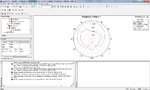
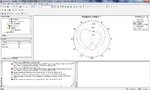
I am new to HFSS. I am trying to simulate metamaterial spiral antenna. The paper I am following is attached along with my hfss project files. I want to get similar gain vs frequency and radiation pattern plots but I cant get it. Can anyone let me know where in my design I am making the mistakes? Thanks.
 

Attachments

  • metamaterial spiral antenna.rar
    70.4 KB · Views: 132
  • Dual-band Counter Circulary Polarized Radiation from a Single arm metamaterial based spiral ante.pdf
    952.2 KB · Views: 123

hi ihos2,
i want to design metamaterial based microstrip antenna, can help me to design how metamaterial based antenna,any document related to that then pls send me my email id-hitesh.mathukya@gmail.com
 

I took a look at your HFSS file. Immediately I noticed an error with they way you set up your infinite sphere. You only have 1 step in-between 0 and 360 degrees. That means when you plot any type of radiation plot you are only going to see one point. You should increase the number of steps. The number of steps depends on how much your radiation plot changes in the phi/theta direction.

Cesar
 

Hi Cesar,
I thought the number of steps was how to increment theta/phi between the start point & end point (0 to 360). So i used 1 so that I can get a smooth plot with 1 degree incrementation of theta with phi=0. These r the patterns I get.
 

Attachments

  • 30step.jpg
    30step.jpg
    238.4 KB · Views: 124
  • 1step.jpg
    1step.jpg
    228.9 KB · Views: 109

Yes, you are right. I read it wrong. I will look at your file again for any errors.
 

Thank you very much. I am also trying to change a few things like air box dimensions or ground plane (instead of sheets, i used box i.e. thickness). The gain vs frequency graphs are ok (very similar to the journal paper) but the radiation patterns r very different. I dont understand how they get such less cross polarisation in the radiation patterns.
 

Status
Not open for further replies.

Part and Inventory Search

Welcome to EDABoard.com

Sponsor

Back
Top