Continue to Site

Welcome to EDAboard.com

Welcome to our site! EDAboard.com is an international Electronics Discussion Forum focused on EDA software, circuits, schematics, books, theory, papers, asic, pld, 8051, DSP, Network, RF, Analog Design, PCB, Service Manuals... and a whole lot more! To participate you need to register. Registration is free. Click here to register now.

GaAs gated Flip-Flop D-Type

Status
Not open for further replies.

wasm

Member level 3
Joined
Oct 22, 2001
Messages
65
Helped
1
Reputation
2
Reaction score
0
Trophy points
1,286
Activity points
358
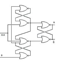
Look at the schematic that follows

38_1160909498.jpg


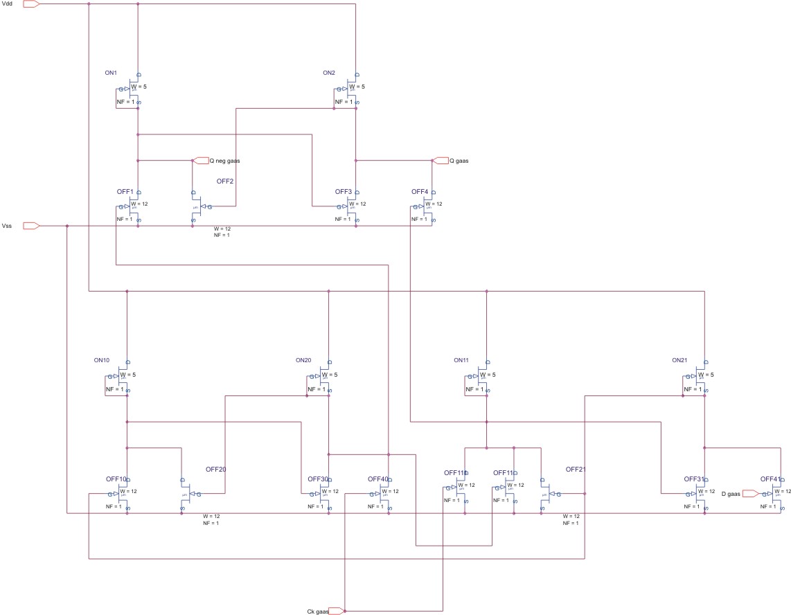
There are critical path to consider to avoid that the circuit doesn't works?


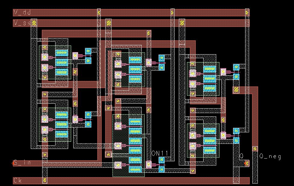
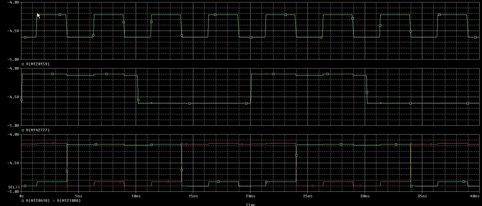
Simulations were made without considering interconnecting transission lines, is it a problem? Consider that the speed of the flip-flop is not crucial
 

To explain the functionality of the circuit above, the following is the block diagram with logic gates

67_1160932829_thumb.jpg


The layout of this circuit was designed by hand, because the adopted foundry has library just for microwave software and the simulations were done on pspice considering ideal interconnections between the FETs

When the input is at level 0 the output follows the input on the rsing edge of the clocl end then store the data indefinitely

The problem is that when the input is high the oputput toggles on each rising clock edge


Do you have any suggestion?
 

Hy Wasm,
can you explain a little bit the behaviour of this circuit ??
It seems to be a JK Flip Flop with shorted inputs so a classical D latches that have to store the data but it seems to me that the network is not so symmetrical as needed for this kind of behaviour, please let we know.
In the meaning time I'll try to simulate this circuit to check your results.
Bye

Etantonio
 

The behaviour is well explained here

**broken link removed**

To simulate the circuit you need the model of FETs (for more information ask me in PM)

Are you sure that simmetry is required?
 

Hello wasm!!! I just checked your schematic and it seems OK. I was wondering if you checked if the rdson of your FETs is low enough to provide the logical levels you need, cause if not you could have diferente ouput voltage levels for inputs like 1-0 and 1-1.

Could you post the layout??
 

The FETs are very small to lower as much as possible the DC power consumption (so rds on can't be so small), but the simulation says what I expect, also for a cascade of six cells

This is the layout

24_1160982519.JPG


Added after 1 hours 43 minutes:

And these are the simulations

In order

CLOCK
DATA
Q with not(Q)

100_1160988764.JPG
 

No one has something to says :-(

I'm losing my faith in you :)
 

Hello again wasm... The simulations seem fine to me. Remember that this FF's output follows the input with the clock's falling edge, I don't see where is the output toggle with the rising edge that you mention.

If those sims are just for the schematic and not for the layout let me know and I'll take a closer look to your circuit

Hope this helps,

diemilio
 

Thanks for your answer diemilio, you are right simulations are fine, the problem is in measurements, and I cannot to reproduce this strange behaviour in simulations

Simulations are just for schematic, because the foundry adopted provides models for Orcad only and as you know it has not a LVS
 

It seems to me that your problem is not related with the circuit's critical path cause when your CLK input changes (keeping the DATA input HIGH) all the other node voltages are stable the only change is given on the 3-input NOR's output, so you're not having any previous changes that could give you unwanted output values. I checked your layout transistor by transistor but everything seems OK.

Sorry wasm, I tried my best.
 

Thanks for you big effort in checking my layout (I know what it means)

OK I undestood what you say, so no critical path could bring to this kind of behaviour


I'm thinking that the problem si related to the measurement setup, we are RF (microwave) designers and our instrumentation is far away to make this kind of measurement reliable :-( ...
 

Status
Not open for further replies.

Part and Inventory Search

Welcome to EDABoard.com

Sponsor

Back
Top