Continue to Site

Welcome to EDAboard.com

Welcome to our site! EDAboard.com is an international Electronics Discussion Forum focused on EDA software, circuits, schematics, books, theory, papers, asic, pld, 8051, DSP, Network, RF, Analog Design, PCB, Service Manuals... and a whole lot more! To participate you need to register. Registration is free. Click here to register now.

Full-Wave Bridge Rectifier

Status
Not open for further replies.

Arif Syazwan

Newbie level 6
Joined
Nov 16, 2013
Messages
11
Helped
0
Reputation
0
Reaction score
0
Trophy points
1
Activity points
80
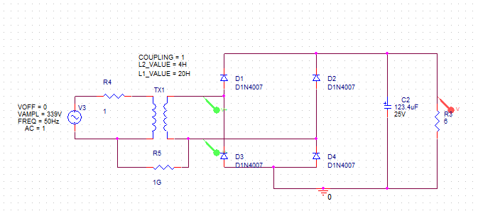
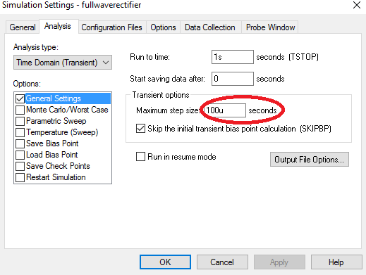
I am attempting to design a Full-Wave Bridge Rectifier using Orcad Pspice 16.6
transformer.JPG

Vrms = 240(339.5Vm) at 50Hz and the transformer should produce 110Vrms(155.56Vm)

L1 = 20H
L2 = 4H
K = 1

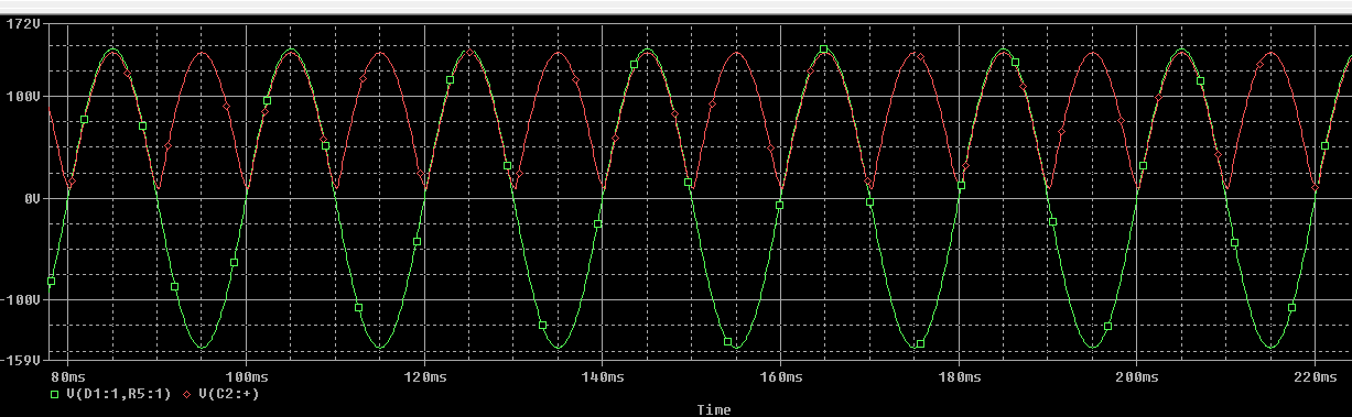
But the simulation result for Voutput = 29V is less than 155.56V
transformer2.JPG
transformer3.JPG

Here is my calculation for rectifier
Vm=sqrt * 110 = 155.56V

Vdc = 2 * Vm / pi = 99V

R = 155.56^2 / 4000w = 6 ohm

Vripple = Vm * 5%
C = 1/ (2*sqrt3 * (50) * (6) * (7.8)) = 123.4uF

Is there something I'm missing here?
 

Maybe trying to pass 18A through 1A rated diodes - or the resistance of the transformer secondary losing 18V per Ohm.

Also be careful where you measure voltages between, the blue measurement point can only measure a valid voltage to the other side of the transformer secondary.

The peak voltage across the load, ignoring resistive losses is (Vrms * sqrt(2)) - (2 * Vf) where Vf is the forward voltage drop of one diode (assuming it isn't vaporized by the current!)

Brian.
 

On the secondary winding of transformer should appear 107.33 V (RMS) if you set the marker correctly.

R = 155.56^2 / 4000w = 6 ohm
Wrong. This is AC not DC and you can not use amplitude value, instead, RMS.
 

I am wrong, you can assume is a DC wave and so the formula is correct.
 

I believe that if your remove the ground from your primary (connect a 100G ohm resistor from PRI-SEC to have a path to ground), the circuit might do what you want.
 

yeah. I recheck my calculation by refer power electronic book. I have done a right calculation.
 

I believe that if your remove the ground from your primary (connect a 100G ohm resistor from PRI-SEC to have a path to ground), the circuit might do what you want.

im still getting the same output
vtran.JPGvtran2.JPG
 

I wonder who you managed to get a transient simulation with so few points? Default PSpice settings will hardly produce it. Anyway, set minimal time step to e.g. 10 or 100 µs.

Secondly there's obviously an initial transient that didn't yet decay inside the displayed time interval. I presume the analysis starts at t= 0, show a longer time interval or start display after an initial delay.

Finally, please disclose the transformer parameters.
 

Hi,

Primary side is directely connected to the signal source. So it should be correct.

What does the differential measurement of the secondary on the scope show?
(Single measurement against GND may show wrong results)

For first tests don't use the capacitor.

The voltage reading "29V"...what is it? Average? RMS? Actual?...

Vdc = 2 * Vm / pi = 99V
That's the formula for calculating the average voltage of a rectified sine without capacitor (but with resistive load).
With capacitor the formula is not true anymore.
Without resistive load the voltage may be floating between the peaks of the sine. A resistive load gives reliable results.
A scope picture should show.

In your scope picture you see only the first milliseconds after switch ON. But you can see the "unsymmetric" waveform becomes more and more symmetric. How does the waveform show after one second?

Klaus
 

I think 20H primary inductance is inconsistent with 50Hz and 230V input for 4kW power. Please verify.
 

I just did a rough estimate: 2*pi*f*L=6180 ohm; looks too high.

4000W at 50Hz; 80W per cycle. Magnetic energy is 0.5*L*I^2=80 and that demands that primary current should be around 3A.

This agrees with 240V *3A=7200W; something is obviously wrong but you see my point...
 

Unfortunately I overlooked the transformer specification in post #1.

Magnetizing inductance of 20 H isn't realistic but doesn't cause any problems.

There's apparently a hidden problem in the simulation setup, the results are completely implausible and can't be reproduced in a standard SPICE simulation, e.g. using LTspice.
 

You can increase R3 to 60R and the simulation will be fine. You are just overloading the transformer.
 

This is your circuit and the settings. Looks like your filter is not very good one. Also the D1N4002 diodes did not gave good result (distorted output of transformer but not like your simulation... a trapezoid wave maybe) so I have changed them.


Status
Not open for further replies.

Part and Inventory Search

Welcome to EDABoard.com

Sponsor

Back
Top