Continue to Site

Welcome to EDAboard.com

Welcome to our site! EDAboard.com is an international Electronics Discussion Forum focused on EDA software, circuits, schematics, books, theory, papers, asic, pld, 8051, DSP, Network, RF, Analog Design, PCB, Service Manuals... and a whole lot more! To participate you need to register. Registration is free. Click here to register now.

Find an opamp for an special range

Status
Not open for further replies.
How you told that ? ( at 17 MHZ ? ) can you clarify it , please ?
Please see below.


- - - Updated - - -

Here is another picture.

The green lines show what happens if we make an amplifier with a gain of 20 dB:
  • Loop gain = unity at 2.5MHz
  • Phase shift at 2.5MHz is 110 degrees
  • Phase margin = 180 - 110 = 70 degrees
  • The amplifier is stable
The red lines show what happens if we make an amplifier with a gain of 6 dB:
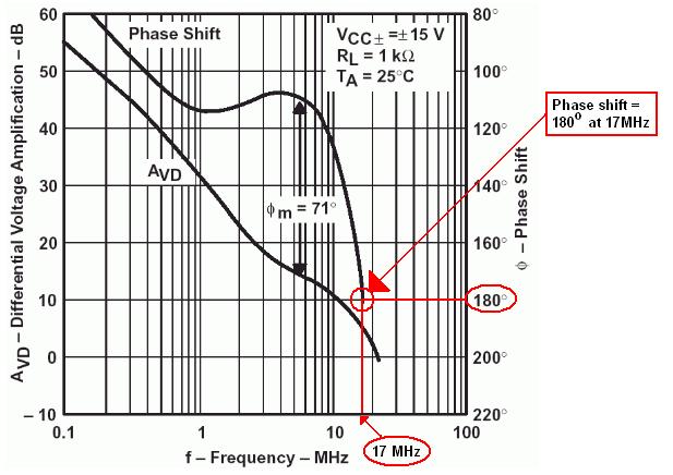
  • Loop gain = unity at 17MHz
  • Phase shift at 17MHz is 180 degrees
  • Phase margin = 180 - 180 = zero
  • The amplifier is unstable. It may oscillate
The blue lines show what happens if we make a unity gain buffer:
  • Loop gain = unity at 22MHz
  • Phase shift at 22MHz is much more than 180 degrees
  • Phase margin is much less than zero
  • The buffer is unstable. It will oscillate
 
Dear goldsmith
Hi my friend

If you try to make a buffer (Vin- shorted to output) then a homemade (using discrete components but without compensation capasitor) opamp will start to oscillate. It will oscillate due to the short between input and output. It is easy to grow an unwanted signal due to high frequency phase shifts between Vin- and output, when Vin- is getting all of the output voltage.
Now if you try to make a X100 non-inverting amplifier (Vin- gets a small fraction of the output) then a homemade opamp will not oscillate. Beacuse it is not easy to grow any unwanted signal between Vin- and output, as Vin- is getting so small fraction of the output.
Now if you try to put a compensation capasitor inside such homemade opamp to make it stable for buffer (unity gain) circuit, then the opamp will become a low slew rate opamp. Thats why, to achieve such unity gain stability, most of the general purpose opamp's slew rate is reduced intentionally by the manufacturer.

With best regards
ahsan_eda
 
Last edited:

One more thing:
It is possible to make a stable unity gain buffer with an opamp that is not unity gain stable. The trick is to reduce the feedback factor without increasing the closed loop gain. The circuit below shows one way to do this.


Thats why, to achieve such unity gain stability, most of the general purpose opamp's slew rate is reduced intentionally by the manufacturer.
With best regards
ahsan_eda

Just a small correction: It is not the slew rate that is reduced "intentionally", but the small-signal open loop phase response.
And - as a consequence of this - also the large-signal properties (slew rate) are influenced.

- - - Updated - - -

One more thing:
It is possible to make a stable unity gain buffer with an opamp that is not unity gain stable. The trick is to reduce the feedback factor without increasing the closed loop gain. The circuit below shows one way to do this.

Yes, good remark. This modification is known as one of the methods for "external frequency compensation" .
However, surprisingly it is not often mentioned in the literature.
 
  • Like
Reactions: FvM

    FvM

    Points: 2
    Helpful Answer Positive Rating
Just a small correction: It is not the slew rate that is reduced "intentionally", but the small-signal open loop phase response.
And - as a consequence of this - also the large-signal properties (slew rate) are influenced.
Thanks for the correction.

Yes, good remark. This modification is known as one of the methods for "external frequency compensation" .
However, surprisingly it is not often mentioned in the literature.
I think it is not often mentioned in the literature due to its high offset error (for this circuit, it is eleven times) at the output.
 
Last edited:

I think it is not often mentioned in the literature due to its high offset error (for this circuit, it is eleven times) at the output.
It's more often used with a RC series circuit between In+ and In- and doesn't increase the offset then, but still the high frequency noise gain.
 
  • Like
Reactions: LvW

    LvW

    Points: 2
    Helpful Answer Positive Rating
Status
Not open for further replies.

Similar threads

Part and Inventory Search

Welcome to EDABoard.com

Sponsor

Back
Top