Continue to Site

Welcome to EDAboard.com

Welcome to our site! EDAboard.com is an international Electronics Discussion Forum focused on EDA software, circuits, schematics, books, theory, papers, asic, pld, 8051, DSP, Network, RF, Analog Design, PCB, Service Manuals... and a whole lot more! To participate you need to register. Registration is free. Click here to register now.

FFT Implementation on Spartan 3E xc3s100e-5vq100

Status
Not open for further replies.
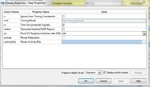
Your problem is here:

Number of Slices 4386 out of 4656 94%

You need additional slices for routing, and ISE cannot find a way to route your logic with only this 6% remaining slices. By the way, you are using a XC3S500E (which has 4656 Slices), not a 100E.

You need to use less slices. Better way to accomplish this is removing some register, using less pipelines, using less distributed memory (maybe using additional BRAM instead distributed RAM?), or having a better use of your flip-flops (using enable when possible, using flip-flop reset instead zero attribution).

No, the number of occupied slices isn't necessarily the issue. I regularly see 90%+ slice utilization. A more telling number is the LUT % (~61%) and the register % utilization (~50%). When par runs it won't pack slices with both FF and LUTs occupied if there is space to spread things out.

- - - Updated - - -

Just dawned on my that the OP should check if the design has a unusually large number of control sets (i.e. clock/reset/enable groups) If there are a large number of them par can't pack registers with different control sets into the same slice. If this is the case one option might be to enable XST's reduce control sets in the advanced tab (though I'm not sure if this is something available for a Spartan 3E part). Basically this XST option converts resets/enables into LUT instead of using the dedicated pins.
 

files
==============================
 

Attachments

  • ifft_pinout_report.pdf
    182.1 KB · Views: 76
  • map_properties.JPG
    map_properties.JPG
    50.7 KB · Views: 62
  • ifft.txt
    1.1 KB · Views: 52

Set all three of these to no in the XST properties, which will force all these functions into the LUTs instead of the dedicated logic.
-use_clock_enable Yes
-use_sync_set Yes
-use_sync_reset Yes
This will ensure you only have a few control sets. See if this makes a difference in par results. I would also change the -opt_mode to balanced (default). Please do these two things one at a time. First change the options to no and see if that makes a difference, resource utilization of LUTs should increase, which should both spread logic out due to more LUTs used and should also reduce local congestion from the routing of the clock enable and resets.

You did exactly what I didn't want, you gave me a list of pins. I want you to do some actual work and interpret the pin out so I don't have to go through the list and figure out exactly where the pins are located on the die. If this was a project I was getting paid to do then I'd have no problem with doing this, but as I'm not getting paid for this job I'd like you to do the tedious work.

So on the die what signals (designated Input, Output, Bidirectional) are on the following sides (going clockwise from 12): top-right, right-top, right-bottom, bottom-right, bottom-left, left-bottom, left-top, top-left. You may have to go into planahead or FPGA editor to see where they are physically located or spend some time in the documentation to find the appropriate package die location information.

regards
 

thanks ads-ee,

I will work on your suggestions.
thanks again

regards
 

Forgot to mention if you are using asynchronous resets, make them synchronous, or at least make most of them synchronous and keep the ones you absolutely need to be asynchronous (i.e. reset synchnronizers). If you don't do this you'll still end up with extra control sets for the registers with resets.
 

Haven't checked mrfibble's youtube...

In this case the reason it will help is the asynchronous reset pin is implemented as part of the register in the slice. As this pin is a "special" feature it has limited routing resources to reach it. By turning off the -use_sync_set No -use_sync_reset No you've eliminated the use of the synchronous use of the special hardware reset input to the register but it won't eliminate the asynchronous ones.

What we are trying to determine is if the design has congestion due to the use of the special feature pins of the register by moving the features (clock enables, reset) to the LUTs. This will lower the maximum clock frequency, but as you don't even have clock constraints that isn't an issue. I'm assuming you just want it to "fit".

Of course you could go into FPGA editor and look at the routing and determine why the congestion is so bad in the locations that are referred to in the reports, but that is a much more advanced methodology. FYI, I don't particularly like doing that and avoid it myself.

regards
 

Status
Not open for further replies.

Part and Inventory Search

Welcome to EDABoard.com

Sponsor

Back
Top