rfmatt
Newbie level 1

- Joined
- Jun 10, 2014
- Messages
- 1
- Helped
- 0
- Reputation
- 0
- Reaction score
- 0
- Trophy points
- 1
- Activity points
- 17
Hello, I have a question about the simulation of large dielectric structures with FEKO, with particular reference to RADOME simulation.
My objective is the evaluation of the effect of a large dielectric radome with a size of ~10 lambda on the pattern radiated by an antenna placed inside the radome structure.
As a preliminary analysis, I have modelled a simple lambda/2 dipole and I have placed it inside an hemispherical radome shell.
Since my structure is electrically large, I have chosen to use the Physical Optics (PO) solver implemented in FEKO.
My problem is that the results show that that almost all the field radiated by the antenna is reflected back by radome, regardless of the relative permittivity of the radome structure.
Let me show it with an example
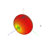
The following figure shows the field radiated by the dipole without the radome (the dipole is directed along the x axis)

Fig. 1 - Dipole in Free Space
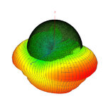
When I add a radome with a relative permittivity equal to 2 (i.e. the green hemisphere shown in Fig. 2), almost all the radiated field is reflected back

Fig. 2 - Radome Enclosed Antenna (radome epsr=2)
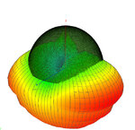
If I lower the relative permittivity of the radome from 2 to 1, the radome should be transparent and the pattern of the dipole should not be affected. However, also in this case almost all the radiated field is reflected back by the radome, as shown in Fig. 3

Fig. 3 - Radome Enclosed Antenna (radome epsr=1)
I have checked all the parameters of FEKO without being able to solve my problem. I would be very grateful if someone could give me some hints about the modelling and simulation of radome or electrically
large dielectric structure with FEKO by using the physical optics (PO) solver.
My objective is the evaluation of the effect of a large dielectric radome with a size of ~10 lambda on the pattern radiated by an antenna placed inside the radome structure.
As a preliminary analysis, I have modelled a simple lambda/2 dipole and I have placed it inside an hemispherical radome shell.
Since my structure is electrically large, I have chosen to use the Physical Optics (PO) solver implemented in FEKO.
My problem is that the results show that that almost all the field radiated by the antenna is reflected back by radome, regardless of the relative permittivity of the radome structure.
Let me show it with an example
The following figure shows the field radiated by the dipole without the radome (the dipole is directed along the x axis)

Fig. 1 - Dipole in Free Space
When I add a radome with a relative permittivity equal to 2 (i.e. the green hemisphere shown in Fig. 2), almost all the radiated field is reflected back

Fig. 2 - Radome Enclosed Antenna (radome epsr=2)
If I lower the relative permittivity of the radome from 2 to 1, the radome should be transparent and the pattern of the dipole should not be affected. However, also in this case almost all the radiated field is reflected back by the radome, as shown in Fig. 3

Fig. 3 - Radome Enclosed Antenna (radome epsr=1)
I have checked all the parameters of FEKO without being able to solve my problem. I would be very grateful if someone could give me some hints about the modelling and simulation of radome or electrically
large dielectric structure with FEKO by using the physical optics (PO) solver.