Vermes
Advanced Member level 4
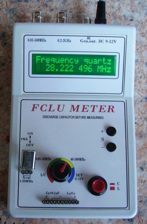
This meter is really universal, because it measures DC voltage, frequency, capacitance, coils inductance, checks the quartz resonators and sends pulses with TTL signal levels, frequencies, which can vary within wide limits. In addition, after adding the adapter, ESR for condensers can be measured. The basis of the device is microcontroller PIC16F873A.
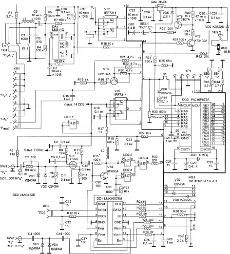
Schema of the device:
Specification of the device – measurement ranges:
- frequencies in MHz:
- “F1” 0,01 … 50
- “F2” 40 … 500
- “F3” 200 … 2000
- capacity:
- “C” from 0,2 pF to 0,1 uF
- “C1” from 0,1 uF to 10 mF
- inductance from 0,1 uH to 5 H
- voltage DC 0,02 … 15 V
- resonant frequency of quartz 0,1 … 30 MHz
- output frequency in generator mode 224 Hz … 1 MHz
- ESR and resistance from 0 to 100 Ω (0,001 Ω resolution) – the measurement is made at 100kHz
- capacity from 5 to 25000 uF
- resistance 0,01 Ω to 50 MΩ (auto range)
- temperature -40 to 105 degrees Celsius (accuracy of 2 degrees)
Current consumption depends on the selected function and range, it is about 14-21 mA at a frequency measurement and about 6-11 mA at capacity and inductance measurement (without LCD backlight).
Measurement errors in mode (without the instability of quartz):
frequency:
Range of “F1” for the period 0,2s, 1s, and 10s – respectively 5Hz, 1Hz and 0,1Hz.
- “F2” 120 Hz
- “F3” 480 Hz
- “C”, “C1” 2%
- “L” 2 … 10%
- “U” 0,05 V
- the software without ESR: L/C – F1 – F2 – U
- the software with ESR: ESR – L/C – F1 – F2 – U – R
ESR – Inductance / Capacitance – Frequency – Frequency – Voltage – Resistance
The individual values of submenu are selected by switches SB1, SB3 and SB4. The display is LCD 2x16 WH1602D. First line displays information about the mode of operation, while the second one displays the measured value.
To measure the frequencies below 500 MHz, signal is fed into the slot XW1. At frequencies above 50 MHz, divisor is used, based on the frequency synthesizer LMX1600TM (DD1). Its work is controlled by a microcontroller (DD3). System DD2 functions as a multiplexer.
The input signal is given to the slot XW1, amplified by the transistor VT1.
In the “F1” mode (Fig.2) there is further amplification of the signal on the transistor VT4 and by gates DD2.2, DD2.4 and resistor R32 is fed to the microcontroller.
In the “F2” mode, signal after amplification on transistor VT1 is fed to the frequency divider DD1 input of the synthesizer, and then after dividing by 24, the output signal is given (1 DD1 output) by gates DD2.3, DD2.4 and resistor R32 to the microcontroller.
In the “F3” mode, measured signal is fed into the slot XW2, and then via the capacitor C4, diodes VD3, VD4 and capacitor C14, it is fed to the input of the second frequency divider in the synthesizer DD1. After dividing by 96, the output signal passes through the gates DD2.3, DD2.4 and resistor R32 to the microcontroller.
Changing the mode from “F2” to “F3” is done by the switch SB3, another pressing this button takes you to quartz resonators placed in slot “ZQX” checking mode.
For measurement of capacitors with a capacity of 0,1 uF and inductive coils, generator system on the comparator DA1 (LM311D) is used. The signal from the generator output is fed directly to a microcontroller input, which measures its frequency and calculates on the basis values of the measured elements.
In “Calibration” mode, the “parasitic” capacity of the slot XS1 is defined and stored in the microcontroller EEPROM for use in further calculations. The program to calculate the values of elements of the circuit, which consists of inductor L1 and condenser C6, according to the mathematical model, assuming that the coil and condenser temperature ratios are constant. If after turning, the meter indications are different from zero, this means that the oscillator frequency changed and is not equal with the value that was saved and stored in the microcontroller EEPROM during the previous calibration. Using this model, the adjusted values of the elements L1, C6, the new value of the frequency (so-called “zero”) can be calculated. The calculations take into account the X6 coefficient and the oscillator frequency change (in %) that made change in the capacity of the capacitor C6.
The capacitance measurement of the capacitors 0,1 uF to 10 mF can be made by transistor VT3. Through resistor R22 from the microcontroller output a low level is fed to the transistor VT3, the transistor is opened and condenser measured (terminals of the terminals 8 and 9 of the slot XS1) is loaded. Then, from the microcontroller output a high level is given, transistor VT3 is clogged and the measured capacitor is discharged through resistor R13. Discharge time is measured by the microcontroller, and since it clearly depends on the capacity of the condenser, the microcontroller calculates the capacity based on known relations.
Measurement of DC voltage (voltage mode) in the range from 0 to 15 V is realized by specifying the slot XW1.
To set the “generator”, we have to enter into “Voltage” mode and press the SB3 switch. In this mode, the transistor VT3 operates in a switch on the socket “Fout” mode (8 and 10 contacts XS1 slots) the signal is given at TTL level at frequency Out=produces TTL level and frequency Fout=Fxt (4mn), where Fxt – the frequency of the quartz resonator of the microcontroller, that can take (adjustable in menu by the L/C switch) values of 1, 4, 16 and the parameter of value (adjustable by SB3 and SB4) in the range from 1 to 256. These values are displayed in the upper right corner of the screen, in the second line – the output frequency signal.
The instrument is powered by accumulators. The supply voltage for all circuits is stabilized by the controller DA2. It is also possible to use an external power supply of voltage 7 … 15 V, which should be plugged into the socket XS3. In this case also automatic backlight of the LCD turns on. While powering from an external source, also accumulators are charged. The indicator of accumulators' charge is visible all the time on the display, as the battery symbol. When the accumulator is discharged, the empty symbol flashes. To charge the accumulator without removing it from the device, use the power supply with voltage of 12 … 15 V and press SB2 button. When the accumulator is charged, an indicator in the galvanic cell image is replaced by the symbol “Z”. Most elements of the instrument, except the LCD display, diodes VD7, VD8, sockets and potentiometer R33 are mounted on double-sided PCB.
LMX1600TM chip can be changed to LMX1601TM, but limit of the measured frequencies in “F3” mode would be reduced to 1,1 … 1,2 GHz.
Microcontroller PIC16F873A can be replaced with PIC16F873, PIC16F876A. System LM311D of any series (uA, LM, etc.) in the housing SO-8, transistors MOSFET IRF7314 – IRF7316.
LCD display, any type, that supports the HD44780 protocol, the organization of 2x16 characters.
Relay K1 – SIL05-1A72-71d (Meder Electronic) with integrated protective diode or SIL05-1A72-71 (then add an external diode in parallel to the coil).
Sockets XS1, XS2 are fragment of precise base for chips. XW1, XW2 – CP-50-73FV or others, such as SMA.
Coil L1 is a choke CECL-100/260 101k (100 uH), coil C2 – for surface mount LQH32M size 1210. Capacity of the capacitors C6 may be in range of 510 … 680 pF, with a very small temperature coefficient.
The capacitor C1 has a capacity of 1000 … 2000 pF. BFR93A transistor may be replaced by any other low power and high frequency (at least 900 MHz) in SOT-23 housing.
Transistor VT3 should have h21E factor not less than 150.
As the quartz resonator, 4 MHz – HC49U with high thermal stability was used. The measurement error depends on it.
Programming the microcontroller using XP1 connector with help of IC-Prog an AN589 adapter, jumper S1 has to be removed. When programming the controller, the configuration bits WDT, PWRT should be set and then the type of generator selected – XT.
Installation and start:
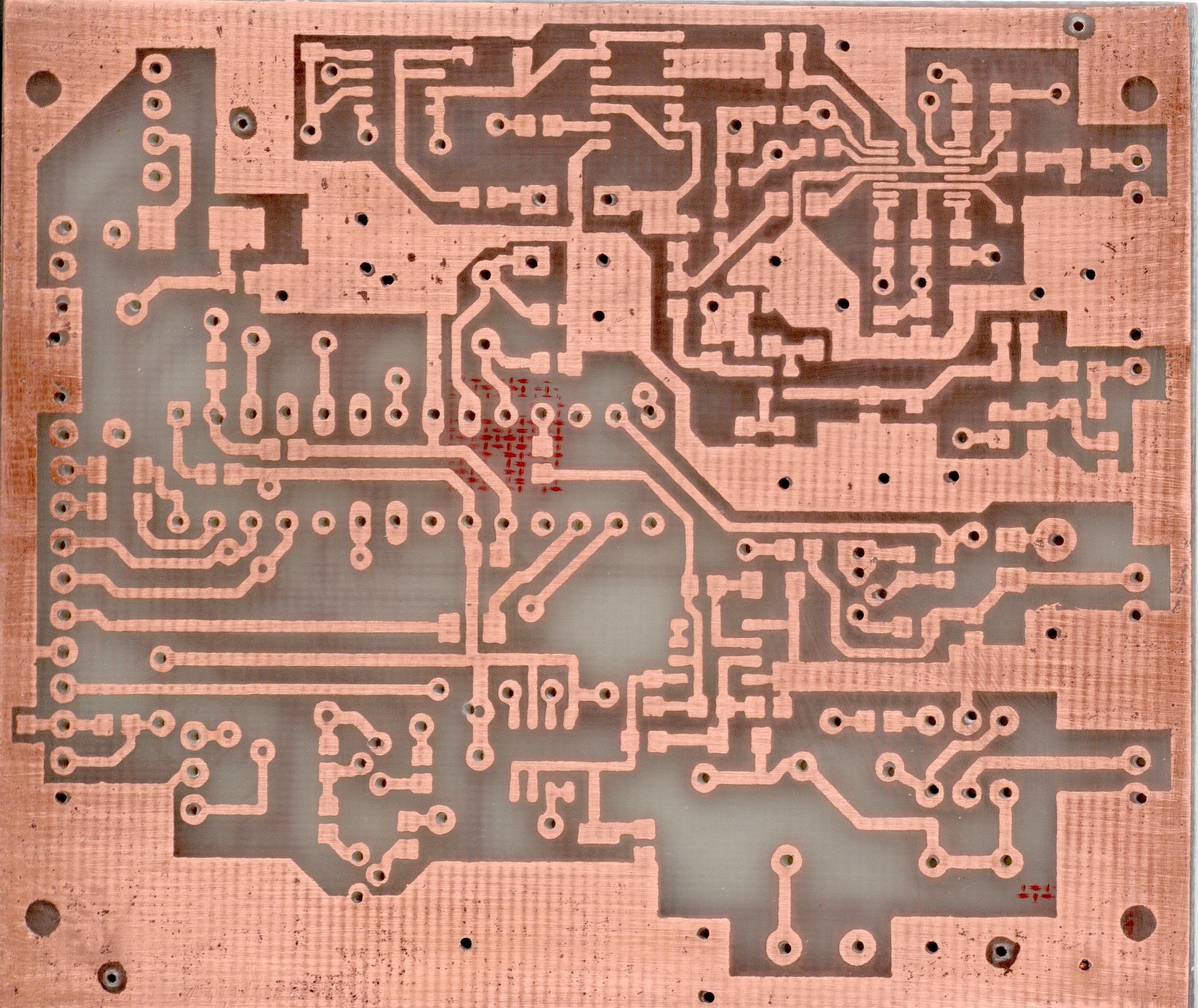
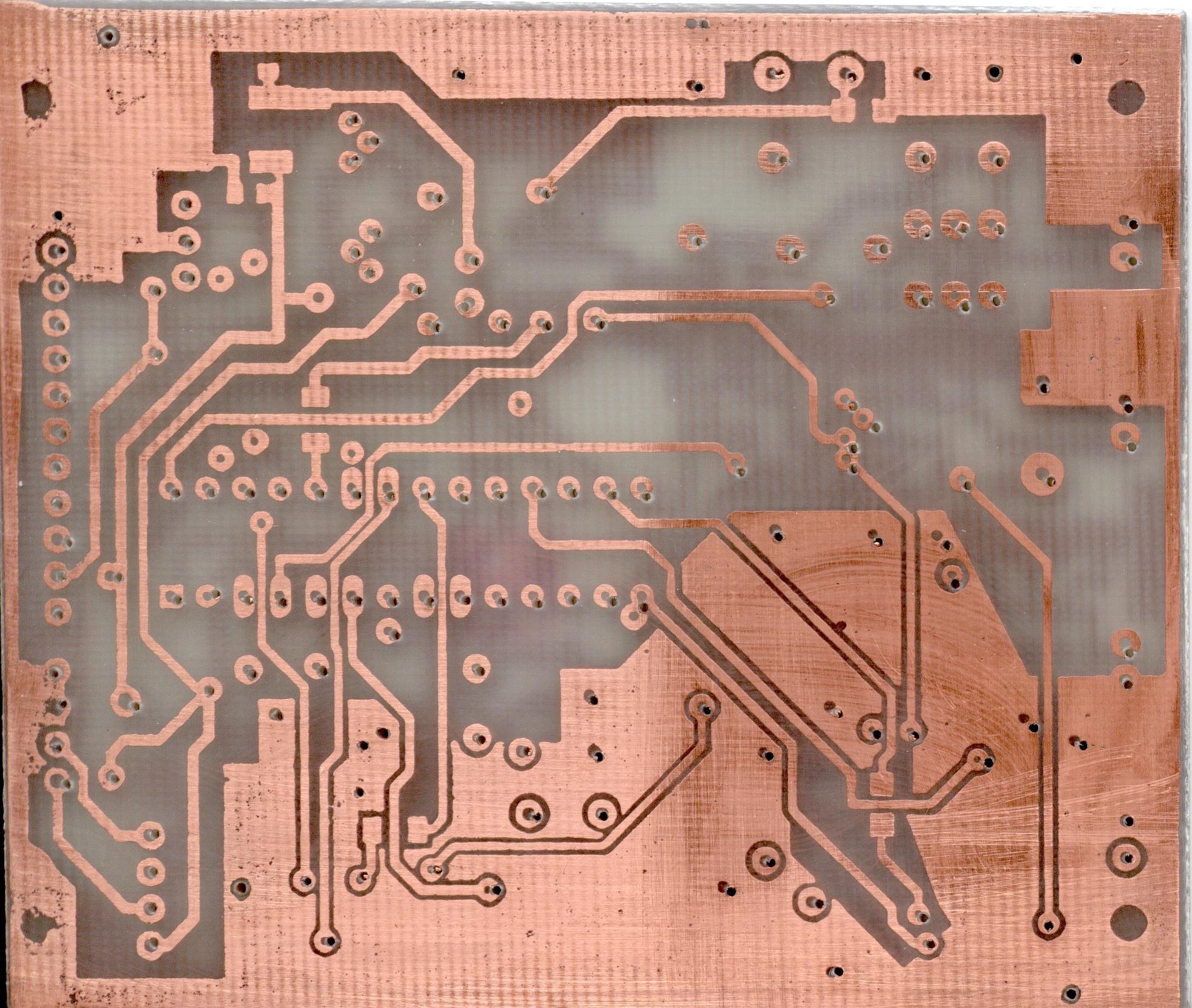
Printed plates:
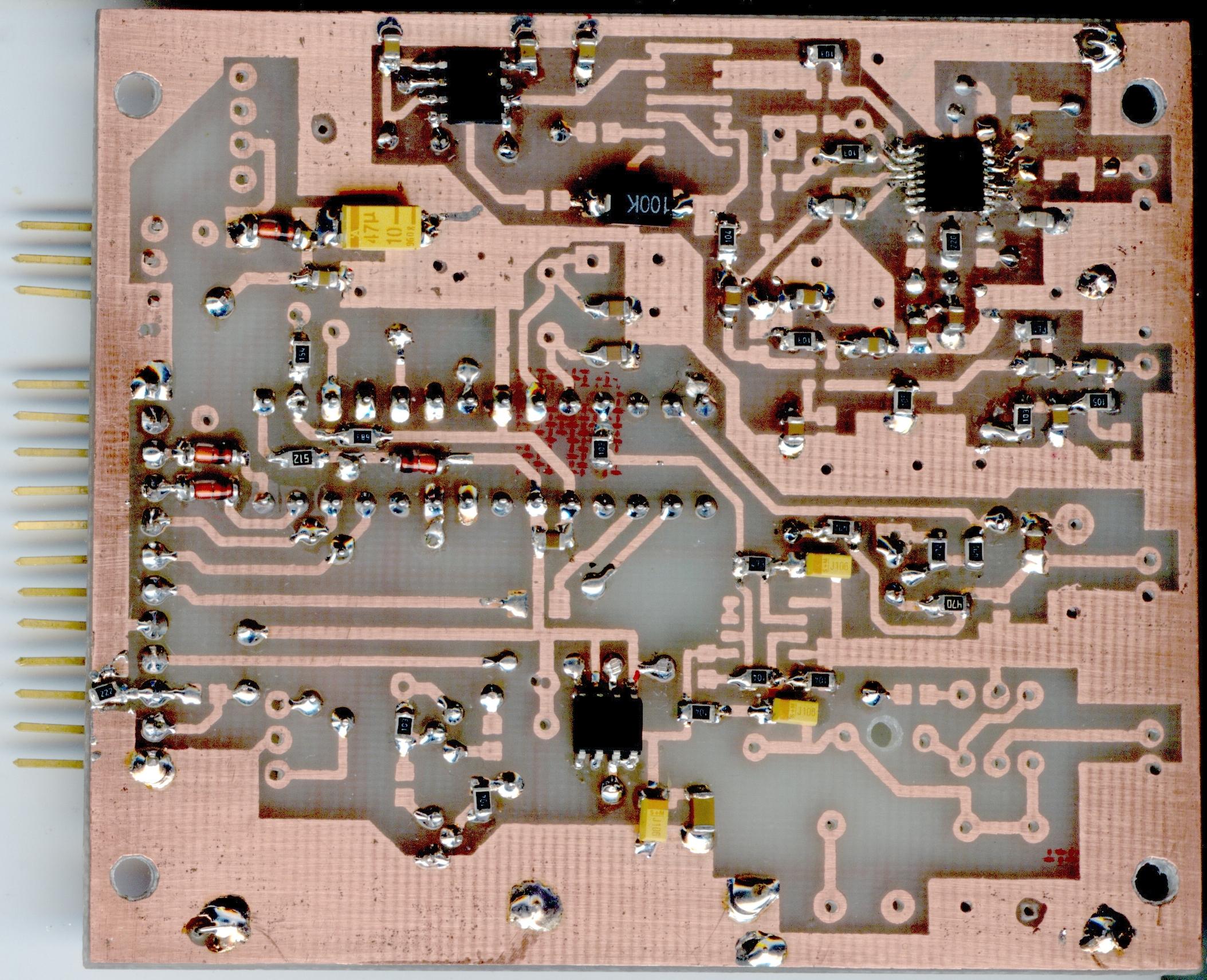
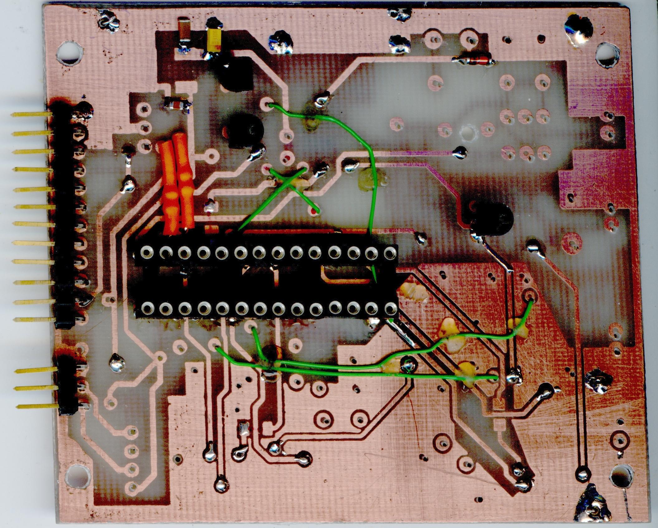
Initial stage of construction:
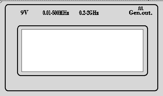
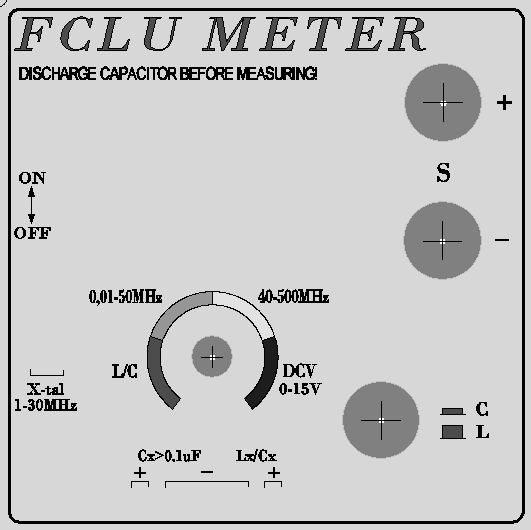
View of the front panel and masking for LCD, made in FrontDesigner program
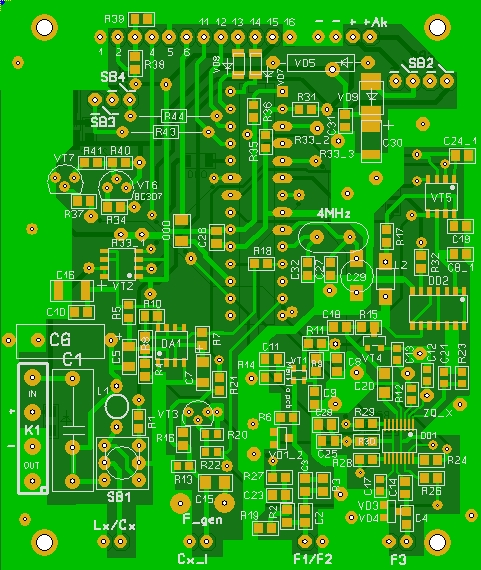

View of plates in the SprintLayout 5 program
Assembly of components and the order is arbitrary, but it is better to start with the microcontroller, adjacent parts and LCD. Determine the values of the contrast with the resistor R39. Also assembly potentiometer may be used. Then assemble the elements of the generator with LM311. When pressing “L/C” on output 7 of the LM311D system, there should be a rectangular signal with a frequency of 750 … 850 kHz.
In the “F1” mode, in the absence of the input signal, selection of the resistor R15, low level of the gate DD2.4 output should be set.
In the “F2” and “F3” modes, in the absence of the input signal, self-oscillation system, frequency dividers DD1 system should be checked.
The battery charging current is set via the resistor R34, and the rate of voltage of the charging indicator via choosing the resistor R31 value.
After installation, the whole plate should be carefully checked.
For proper operation of the instrument, it is required to make a few constants to EEPROM memory of the microcontroller. To do this, press the SB3 and turn the power of the device, then release the button. By changing the value of the potentiometer R33, select the number of constant from X0 to X9 and change the value by buttons SB3 and SB4. Changed values are automatically saved in the microcontroller EEPROM, after changing.
Initial values and the importance of constant:
- X0=1000 – C1 capacitance value in pF
- X1=1000 – changes not reccomended (correction of the inductance measurement)
- X2=0000 – synthesizer type DD1 0 for LMX1600 and 1 for LMX1601
- X3=1539 – adjusts the indication of DC in the “Voltage” mode
- X4=0004 – operation mode and language
- X5=4.000.008 – frequency of the quartz resonator – values from 3.868.934 – 4.131.068 set each 4 Hzc
- X6=0060 – values from 0 to X6=100, the value of less than 50 with a negative capacitor C6 temperature coefficient
- X7=1472 – corrects the proper readings when measuring the capacity
- X8=default
- X9=default
- X4=0, 2, 4, 6 – for the English version of the device (English menu)
- X4=1, 3, 5, 7 – for the Russian version of the device (Russian menu)
- X4=0, 1, 4, 5 – initial measurement time of 0,2s for the “F1” mode
- X4=2, 3, 6, 7 – initial measurement time of 1s for the “F1” mode
- X4=0, 1, 2, 3 – the value of a temperature coefficient C6 positive
- X4=4, 5, 6, 7 – the value of a temperature coefficient C6 negative
The procedure for calibrating the device:
1. Calibration of the instrument starts with the calibration of the frequency counter, giving the model signal 30-40 MHz and then correct the meter indications with a trimmer and constant X=5, so the meter shows the model F. The meter should be set in position F1, 0-500 MHz input, 0,2 sec.
2. Calibration of the constant X0.
- exact (measured by a sure meter) capacity of the capacitor C1 (in pF) should be written into constant X0
- turning the knob of the potentiometer R33, set the “L/C” mode and set the “C” mode by switch
- select the “Calibration” mode. After finishing, there would be 0,00 pF value on the display
- connect the model capacitor (very accurate, e.g. 0,5%) with previously measured with high accuracy
- calculate: Cmodel/Read * X0
- write the result to the X0
4. connect the jumper and make calibration in “Calibration” mode
5. remove the jumper and measure the well-known (very accurate, e.g. 1%) inductance
6. any adjustments can be made by making entries in the X1
Remember! All calibrations are made after heating the meter for 20-30min.
Practical work with the meter:
example:
activate the meter in position C, but the indications are not 0001 but a few pF. Wait several minutes so the meter can heat up. After that, turn into another measurement (e.g. frequency) by the potentiometer knob and immediately turn back to position C. The meter would zero then and adopt the values during calibration – LCD would show 000 pF. Auto-zeroing would also start. Frequency drift of the generator would be automatically compensated. Note that the indication of zero for the capacity measurement would flow to for example 0,1 pF and then the meter would reset it to 000 pF.
Of course, there is no auto-calibration when measuring L, just the generator circuit is open, but switch back to C by the potentiometer knob to another mode and the slide back to C and start measurement L and it would be calibrated. Now the jumper can be put on measuring contacts and the indications should be the L=0000(0001, 0002) uH.
If we want to make very accurate measurements of L and C, the following solution is recommended:
Turn on the meter in C (heat the meter) and calibrate it as described above (the knob on F and back):
- switch to L and put the jumper, calibrate by pressing SB4. Take off the jumper and make the measurement. After a long break the meter would need another calibration and it can measure like before. The accuracy of measurements is a few nH.
- when the exact measurements of C simply calibrate before each measurement (the potentiometer slide to another mode and right back immediately). The accuracy would be 0,1 pF.
Printed plate, ESR adapter

Schema of the ESR adapter

Link to original thread (attachments) – Miernik FCLU - uniwersalny miernik na PIC16F873A