iimagine
Member level 5

- Joined
- Oct 23, 2013
- Messages
- 85
- Helped
- 10
- Reputation
- 20
- Reaction score
- 10
- Trophy points
- 8
- Activity points
- 512
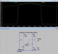
I decided to install a dual battery system in my SUV since I have a spare battery laying around. I bought a PAC-80, 'battery isolator' they called it... Its just really is a solenoid/relay. I had it mounted, all wired up except for the triggering part. I don't want to have it wired to the accessory on or install a manual switch. I want it to trigger on only when the car is running so that the backup battery can be charged, so I designed this circuit:
Base on the Fact that when the engine is running, most alternator puts out more than 13.6V

Output is taken at R4 and will be driving a suitable FET
Output is HIGH when VCC is greater than 13.6V
PAC-80: **broken link removed**
The relay will handle 80 amperes on a continuous basis at 12 VDC and 150 amperes in rush peak or surge.
Switching power must be between 10 and 14 VDC. The relay coil draws less than 1amp when switched on
I think it should work, I'm posting this here for your opinions/improvement before pulling out my soldering gun.
Thanks
Base on the Fact that when the engine is running, most alternator puts out more than 13.6V

Output is taken at R4 and will be driving a suitable FET
Output is HIGH when VCC is greater than 13.6V
PAC-80: **broken link removed**
The relay will handle 80 amperes on a continuous basis at 12 VDC and 150 amperes in rush peak or surge.
Switching power must be between 10 and 14 VDC. The relay coil draws less than 1amp when switched on
I think it should work, I'm posting this here for your opinions/improvement before pulling out my soldering gun.
Thanks
Last edited:


