Vermes
Advanced Member level 4
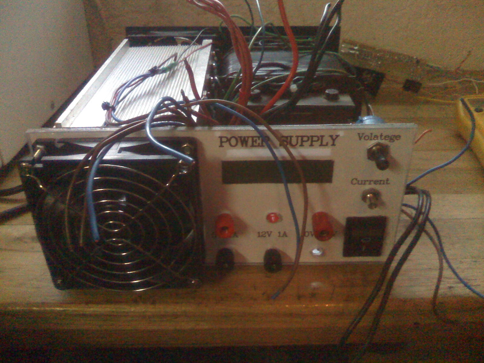
Transformer taken from an old rectifier has a power of approximately 450VA and voltages 2x18V. Heat sink was disassembled from UPS 1000VA. The power supply capacity is 25A and 25V adjustable with multi-turn potentiometer. 6 pieces of TIP142 are mounted on the heat sink. 2 resistors 50W 0,1R connected in parallel act as a resistor through which current is measured and limited in the system.
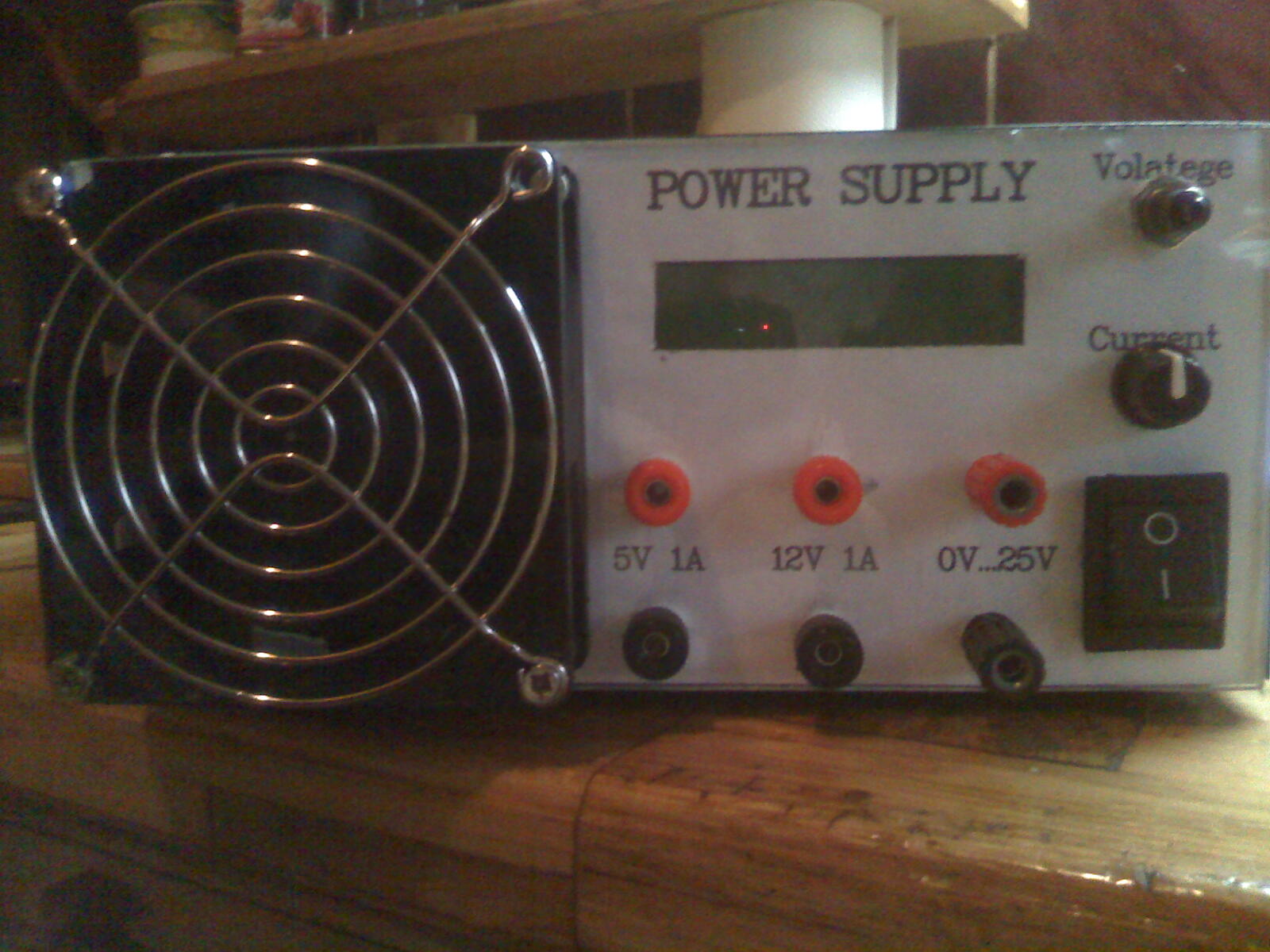
Atmega16 shows on the LCD:
- output voltage
- output current
- set limit current
- temperature of the heat sink (sensor DS18B20)
Fan (2 pieces with dimensions of 92mm) speed adjustment is a 3-step and fans tuns on after the temperature exceeds 30 degrees Celsius and the fans reach fill speed at a temperature of 45 degrees Celsius.
The output voltage is limited to 0 after the heat sink exceeds 85 degrees Celsius.
Additionally, with the adjustable output voltage, 2 left 5V and 12V, both with current limitation 1A.
The power supply dimensions: 100mm x 220mm x 240mm, weight: 12kg

Link to original thread (useful attachment) – Zasilacz Elektronics Lab 25A 0-25V