Vermes
Advanced Member level 4

- Joined
- Aug 2, 2011
- Messages
- 1,163
- Helped
- 0
- Reputation
- 0
- Reaction score
- 0
- Trophy points
- 1,316
- Activity points
- 22,318

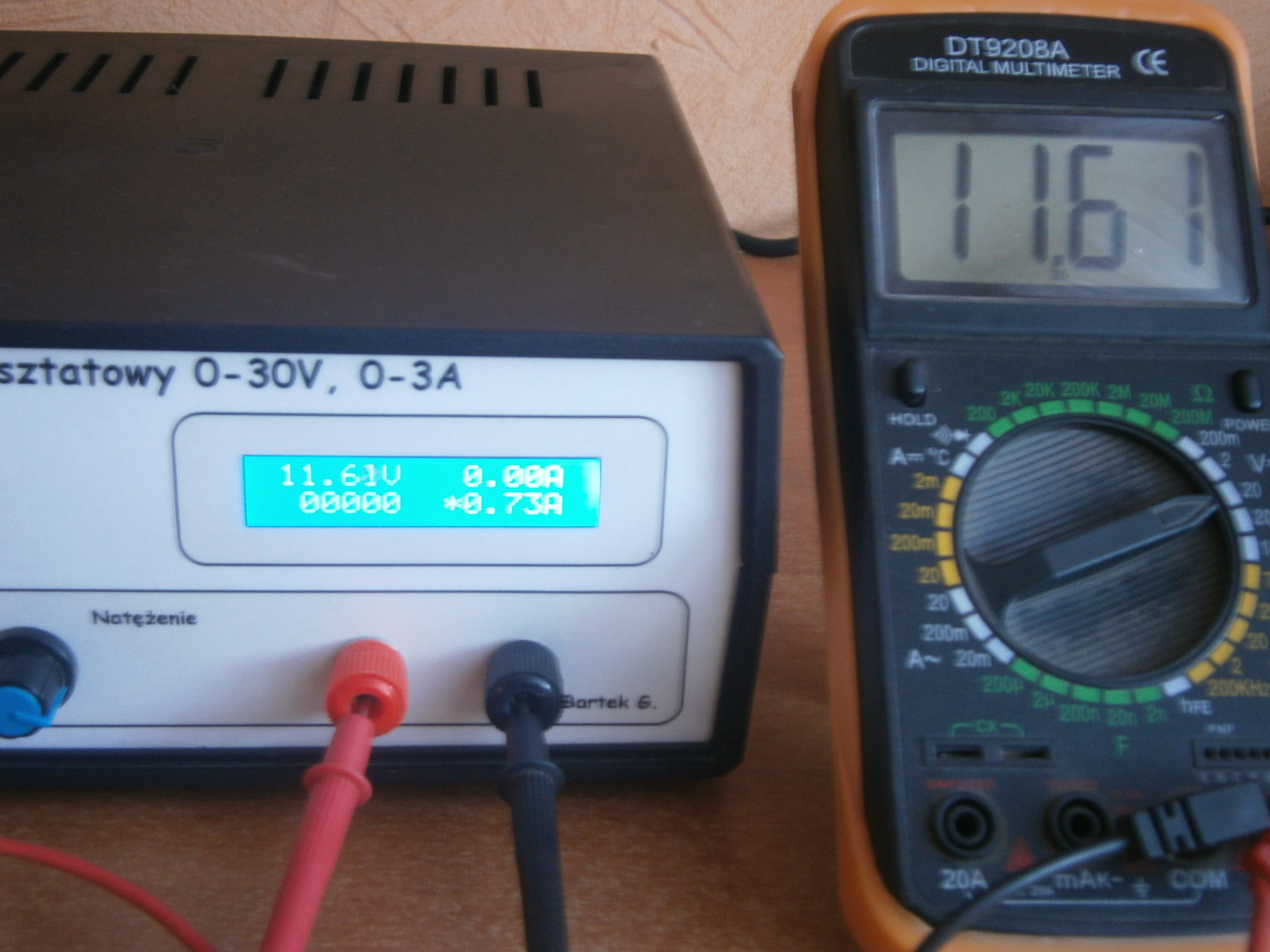
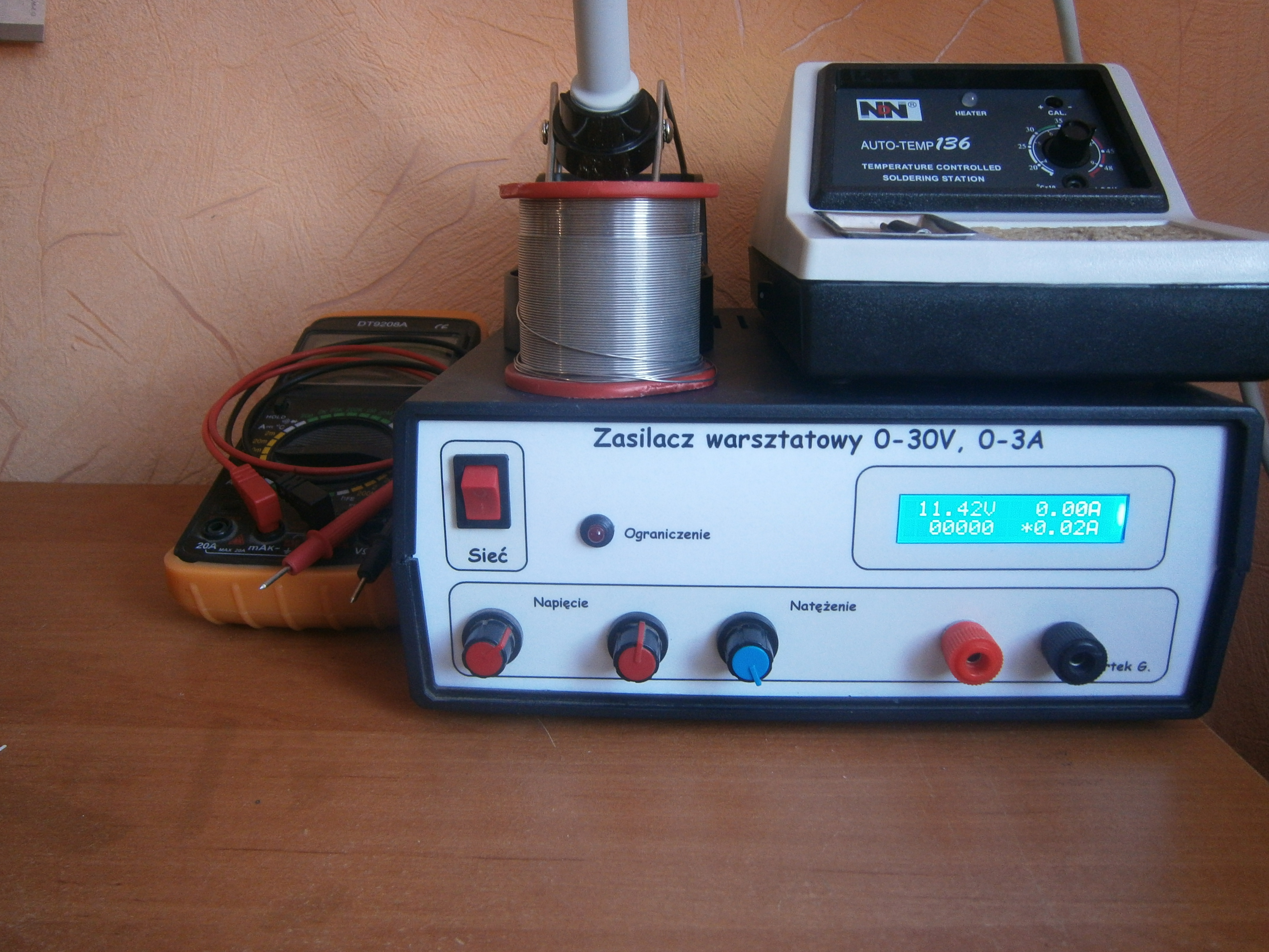
It is a popular lab power supply which can be easily made at home.
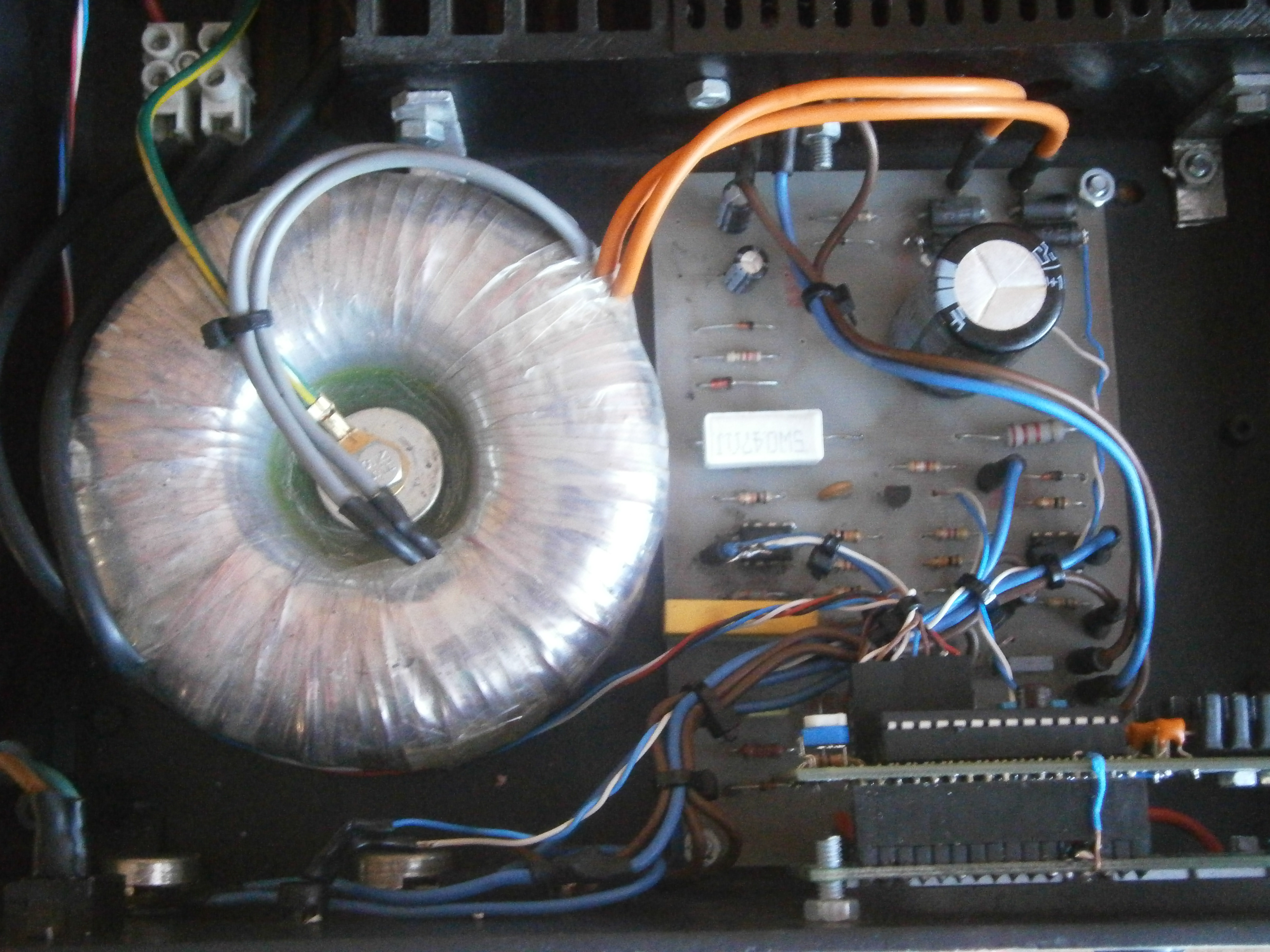
Power supply board:
The circuit is a well-known board from HERE. It is very good for this purpose, although two parts of the circuit were changed:
- transistor 2N2219 was changed to BD135
- potentiometer was added in order to control voltage more precisely
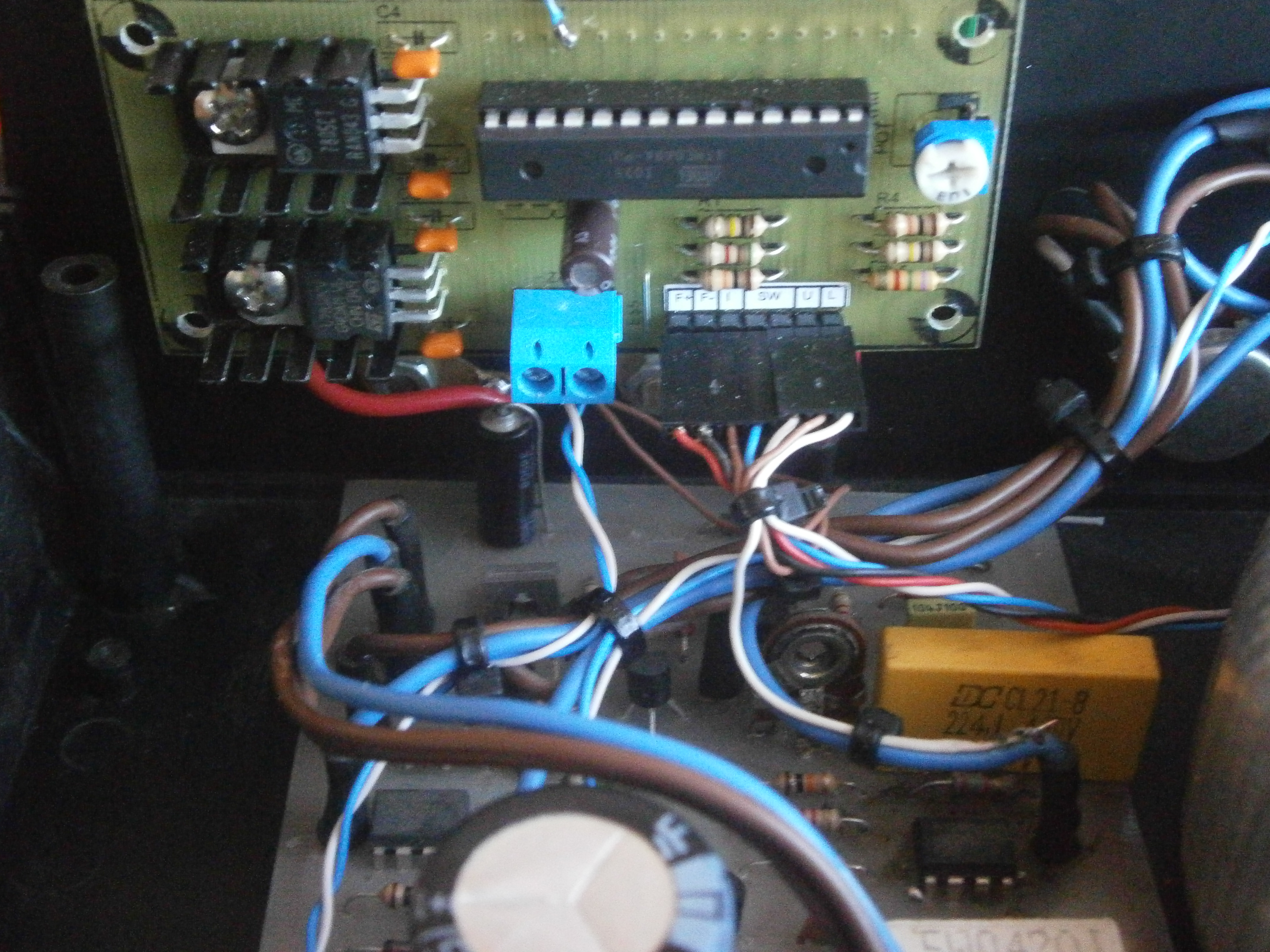
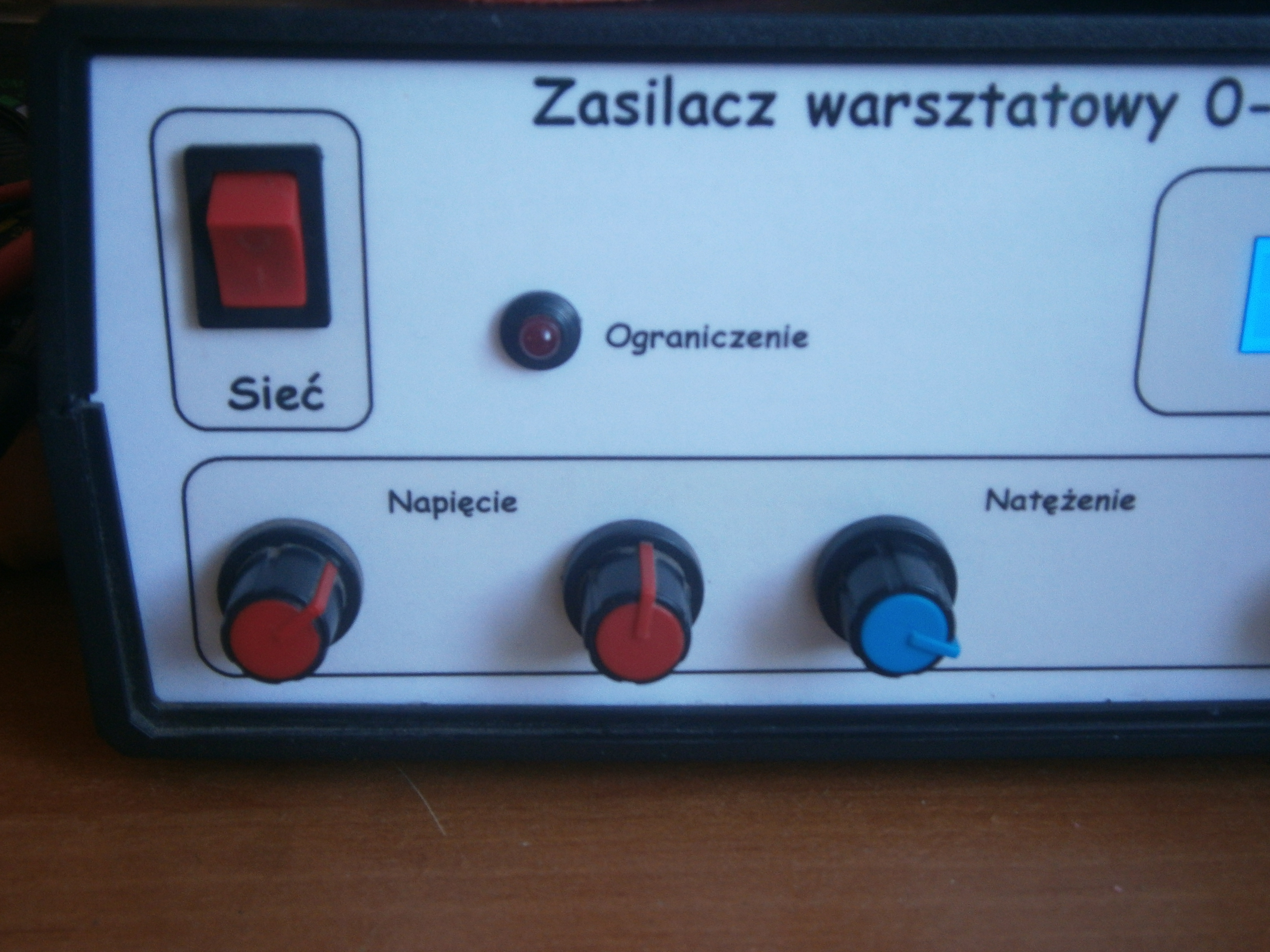
Meter:
The meter is also a well-known one which can be found at: LINK. This power supply uses a version with displaying the current settings. If you want your construction to be a cheaper one, you can resign from the transistor that controls the fan – it is switched on together with the meter. The device uses a cheap thermal regulator.
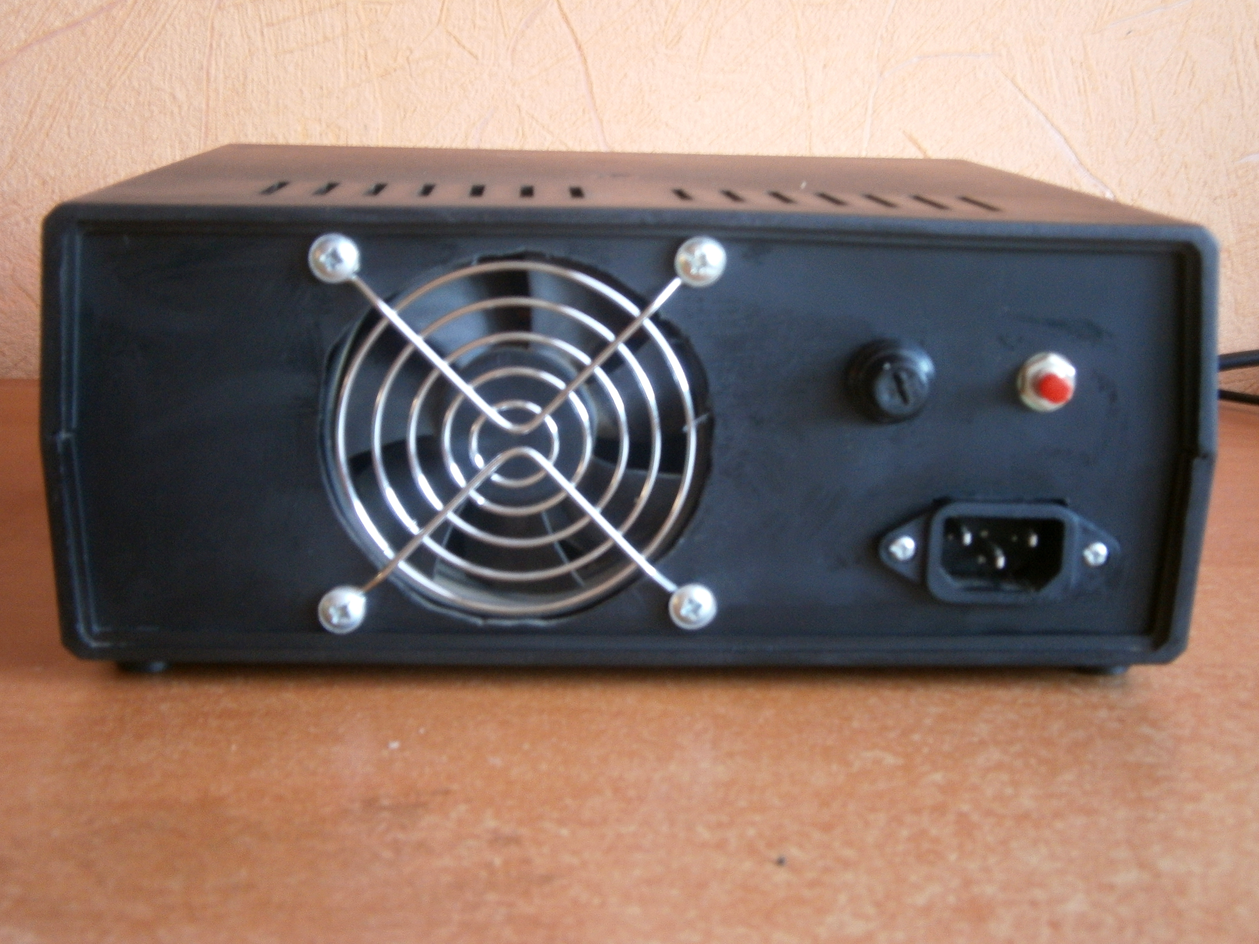
Everything fits in Z-17 housing. Front panel was made in Word, printed and laminated.
Few more pictures:


Link to original thread (useful attachment) - Zasilacz warsztatowy 0-30V, 0-3A
Last edited by a moderator: