Continue to Site

Welcome to EDAboard.com

Welcome to our site! EDAboard.com is an international Electronics Discussion Forum focused on EDA software, circuits, schematics, books, theory, papers, asic, pld, 8051, DSP, Network, RF, Analog Design, PCB, Service Manuals... and a whole lot more! To participate you need to register. Registration is free. Click here to register now.

Driving triac using 2 out-of-phase lines

Status
Not open for further replies.

vishweshgm

Member level 4
Joined
Dec 17, 2021
Messages
74
Helped
5
Reputation
10
Reaction score
7
Trophy points
8
Activity points
950
Hello,

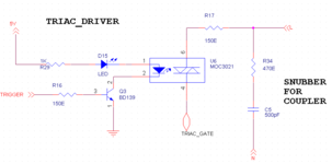
I am trying to make a typical dimmer application (resistive heating coil 3.6kW (230V,16A)) using triac similar to the application shown below:
1650861237620.png

Instead of Hot and Neutral, I plan to use Red & Blue wires of three phase supply. I rigged this circuit in lab and triggerred triac at a point 'X' after a Zero cross pulse is generated (I dont know, technically ZCD is the right term, but the point where Red and Blue waveform intersect, I call it as ZCD point, as that is where I get a edge detection(yellow) on microcontroller)
1650862654243.png


So after every edge detection I control time at which triac is triggerred say that point X is between 0deg & 180deg. As I slowly move from 0 to 180 power delivery is decreasing which is exactly how I want to control. But I want your help to understand from theory point, what is happening here. It was easy for me to understand when there were only 2 lines Hot and neutral. But with this, I am unable to understand if this is right method and also if it is ok to drive triac like this.

Let me know if any more infor required.
 

Solution
Hi,

Plot:
Correct. The orange line i the only line that matters for operation.
Your ZCD also sees (has to!) the voltage of the orange signal (using both R and B). It needs to detect the zero crossing point of the orange signal.

Your conclusion:
I guess you got it now.
As long as all relates to the orange signal you are on the safe side.

Earth potential does not matter.
* R may be connected to earth or not
* B may be connected to earth or not
* Neutral may be connected to earth or not

Klaus
Hi,

Some issues:
* I don´t think it´s allowed to use a 3.6kVA dimmer
* you say "230V, 16A", but are you sure you have 230V between red and blue?
* you say "dimmer" so I guess "phase angle control" ... but your optocoupler-driver shows a "zero crossing circuit".
--> You can´t use "phase angle control" with a "zero cross switching optocoupler"
* for phase angle control the microcontroller needs to know the time of zero cross. Missing in your circuit.

To your questions:
* the optocoupler isolates (electrically) both sides from each other. So the microcontroller does not know (and does not need to know) whether one of the power lines is EARTH or earth related.
(still the mc needs to know the ZC timing)
* you have two power lines, AC. Every time the instantaneous voltage between both is zero it is called "zero crossing". Independent of EARTH or any other reference at all.

Klaus
 

The triac triggers at zero crossing regardless of the exact time the microprocessor triggers it. The zero crossing is detected in the opto-coupler and it is based only upon the voltage across it. You can use it in burst mode where the triac stops and starts for complete cycles but not for phase control.

For phase control, which I think is what you seek, a different optocoupler type is needed, one without a zero crossing circuit and you then need to switch it on at different times after zero crossing has been detected by the microcontroller.

Brian.
 

if you turn a triac on just after the zero crossing it will stay on until the next zero crossing - hence you cannot do phase control this way, as said above you need a different opto, so you can fire at some angle after the zero cross for reduced power ....
 

@KlausST @betwixt : I realize the mistake in question. Now I use MOC3021 with no zcd detection.
1650886052352.png

Here is my zero crossing circuit (yellow signal in the question). (to avoid confisuion I refer to it further as R_n_B crossing circuit)

1650885198220.png

When I get a high edge on this circuit, I start timer and I trigger MOC3021 opto after 5ms(note:50Hz AC). In this case I get triac triggerred and my AC bulb light-on at a medium brightness (I am just using AC bulb to test this in lab). If I reduce 5ms to 1ms, bulb lights brighter. If I increase 5ms to 9ms bulb starts flickering.

So I have a circuit working in (1ms to 5ms part). (from 5ms to 10ms band some where bulb turnoff and then with further delay, it starts flickering.). So I am not sure what is happening. So I wanted to know what is the right way to understand phase control in triac, when 2 out-of-phase signals are at T1 and T2. (any textbook link would also help)

I think if someone can help me get a SINGLE waveform that shows voltage variation of R only w.r.t B most of my confusion gets solved. Below digram shows R & B sine waves voltage variation w.r.t Neutral, but I want R w.r.t B waveform
1650886229678.png

--- Updated ---

I don´t think it´s allowed to use a 3.6kVA dimmer
Sorry, I donot understand. Is it not allowed by any standards? Cause, my customer asked he has a 3.6kW IR heater.
you say "230V, 16A", but are you sure you have 230V between red and blue?
Yea, I measured rms value using multimeter. and it does show 230V line to line.
you say "dimmer" so I guess "phase angle control" ... but your optocoupler-driver shows a "zero crossing circuit".
I realize the mistake. Definitely I want to do phase angle control to control power delivery just like a normal dimmer works on singlephase AC.
 

Attachments

  • 1650885841518.png
    1650885841518.png
    20.9 KB · Views: 89
Last edited:

Hi,
When I get a high edge on this circuit, I start timer and I trigger MOC3021 opto
You should do the same on both edges. For negative half wave and positive half wave equally.


I think if someone can help me get a SINGLE waveform that shows voltage variation of R only w.r.t B most of my confusion gets solved.
Some options:

Since functionally it makes no difference neither for simulation nor for a real circuit: just connect R or B to GND, EARTH, or whatever you like. (in a real circuit you can do this only if the supply is floating)

For simulation: just draw your voltage signal as "R-B" --> subtract one from the other.

***
Keep in mind: The function does not depend on EARTH at all. It will work on the ISS or on Mars or on every other isolated system.

Klaus
 

.... and don't forget the phases will be 120 degrees apart so whichever you choose to sense between, your microprocessor can compensate for the angular shift and the LED turn-on threshold.

On that topic, you need the optocoupler LED forward voltage + the diode forward voltage before the LED even starts to light up and being current driven, there will always be a time lag after zero crossing before enough current can flow to switch the triac on. You can minimize the voltage by connecting the diode across the LED but the effect will be minimal and the current through the resistor doubles. You might get better efficiency by using a capacitive dropper and a much smaller resistor. It would introduce a phase shift but it would be constant and easy to adjust out in software.

Brian.
 

ou should do the same on both edges. For negative half wave and positive half wave equally.
Yes. agreed. Im doing the same.
For simulation: just draw your voltage signal as "R-B" --> subtract one from the other.
Ok, so I used matlab to plot this R-B (orange). This is supposedly variation of R if B is held at 0. It seems alright.
1650952562886.png


Keep in mind: The function does not depend on EARTH at all. It will work on the ISS or on Mars or on every other isolated system.
From plot I understand, driving technique can be same, doesnot matter if R&B is connected or Live&Ntrl connected. It's the Amplitude of sine wave change that needs to be considered while designing a circuitry. Please confirm this conclusion is correct.
--- Updated ---

Matlab plot code. Just for reference
Code:
>> x = sin(2*pi*(50/1000)*[0:79]);
>> y = sin(2*pi*(50/1000)*[0:79]+(2*pi/3));
>> plot(x-y);
>> plot(x);
>> hold on
>> plot(y);
>> plot(x-y);
 
Last edited:

Hi,

Plot:
Correct. The orange line i the only line that matters for operation.
Your ZCD also sees (has to!) the voltage of the orange signal (using both R and B). It needs to detect the zero crossing point of the orange signal.

Your conclusion:
I guess you got it now.
As long as all relates to the orange signal you are on the safe side.

Earth potential does not matter.
* R may be connected to earth or not
* B may be connected to earth or not
* Neutral may be connected to earth or not

Klaus
 
Solution
Hi,
Sorry, I donot understand. Is it not allowed by any standards? Cause, my customer asked he has a 3.6kW IR heater.
Neither "heater" nor "IR" nor "3.6kW" is the problem.
The problem is "phase control" which causes overtones and switching noise in the mains current and and shifts the "higher" current to the end of a sine halfwave.

At least in Europe one needs to keep on regulations to keep the mains voltage "clean".

Klaus
 

At least in Europe one needs to keep on regulations to keep the mains voltage "clean".
Oh! I want to keep mains clean, as I want to build a good product. So please answer What do you suggest that I use for this type of 3.6kW load (basically patio heaters) ? Triac or Mosfet or any other?
 

Re-label a welder with phase control for the task .....?

Keep in mind those guys have been dealing with controlled current delivery
for some time, meet regulations, understand high power control. I was for-
tunate enough to call on 3 EEs, close to retirement, for several years who
knew more than the creator in this area. There are lots of considerations
that go into designs like this, and one does not get that blinking an LED
with a PWM....:) The knowledge of just magnetics alone in the designs
they handled worth its weight in gold. The evolved high freq switching
used to keep component sizes down, filters physically and electrically
manageable......

You can always approach a welding company with the opportunity.


Regards, Dana.
 
Last edited:

Status
Not open for further replies.

Similar threads

Part and Inventory Search

Welcome to EDABoard.com

Sponsor

Back
Top