Continue to Site

Welcome to EDAboard.com

Welcome to our site! EDAboard.com is an international Electronics Discussion Forum focused on EDA software, circuits, schematics, books, theory, papers, asic, pld, 8051, DSP, Network, RF, Analog Design, PCB, Service Manuals... and a whole lot more! To participate you need to register. Registration is free. Click here to register now.

Distorted transient result for 3 temperature for LDO

Status
Not open for further replies.

roki

Member level 1
Joined
Mar 29, 2009
Messages
33
Helped
0
Reputation
0
Reaction score
0
Trophy points
1,286
Activity points
1,545
1.jpg
2.jpg
LDOESR transient 85C.jpg

Hi everyone,

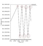
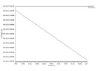
Attached above is the transient result of my LDO with output of 0.9V. The first figure is at 0oC, the second is at 27oC and the third is 85oC.

For 1st figure, the output is very distorted.
For 2nd figure, the is a sudden glitch at the front.
For 3rd figure, the output is going down.

I'm supposed to get a straight constant value.But I do not know the reason of why my results are shaped like that, so please help me understand.Is it parasitic oscillation? if yes, what causes it?

Thank you!

Regards
 
Last edited:

fig 1 : Look at the y scale of your plot: if the "M" suffix stand for milli and nor for mega, the ringing amplitude is very low (<1 nV).
it may be simulation artefact: Check the simulation parameters
fig 2 : same issue ?
fig 3 : same scale remark: for most use, this LDO is perfectly flat !
 
Last edited:

The 'M' stands for milli.
Initially, i disregarded the distorted output shape as it is insignificant in my opinion, but my lecturer insisted i explain the cause of the output spikes/distortions.
What is simulation artefact?
 

The deviations are 0.21ppb (2.1e-10 , which corresponds to <1LSB of a 32bit converter). So it's probably the noise (i.e. the resolution limit) of the 32bit arithmetics of your computer.
 

The deviations are 0.21ppb (2.1e-10 , which corresponds to <1LSB of a 32bit converter). So it's probably the noise (i.e. the resolution limit) of the 32bit arithmetics of your computer.

Hi erikl!Can you please further elaborate as i have never knew about this possibility. I'm blur.
 

The simulation resolution should not be tight by the number of bits of the processor, but by the algorithm convergence limit...
But I agree with eriki: this looks like calculation "noise" (probably rounding)
 

Hmm...if this is cause by "noise", then shouldn't my post-simulation result be distorted too?instead, my post-simulation results are much much better.
i've attached my post-simulation result for your reference.
POST LDOESR trans 0C.jpg
POST LDOESR trans 27C.jpg
POST LDOESR trans 85C.jpg
 

Hi erikl! Can you please further elaborate as i have never knew about this possibility.

It could be the algorithm convergence limit, as gag2000 stated above, SPICE programs however always use the full number domain of the computer. As the voltage deviations are about 1LSB of a 32-bit system, this suggests that a computer with a 32-bit arithmetic has been used.

And then it's the "noise" of the computer arithmetic system, also sometimes (falsely) called "rounding error": in a true 32-bit system, there's no bit#33 , which erroneously could be rounded in the wrong direction. In a 64-bit system, however, results often are reduced to 32-bit size, and in this case the deviations could actually be created by rounding, as gag stated.
 

Status
Not open for further replies.

Part and Inventory Search

Welcome to EDABoard.com

Sponsor

Back
Top