Continue to Site

Welcome to EDAboard.com

Welcome to our site! EDAboard.com is an international Electronics Discussion Forum focused on EDA software, circuits, schematics, books, theory, papers, asic, pld, 8051, DSP, Network, RF, Analog Design, PCB, Service Manuals... and a whole lot more! To participate you need to register. Registration is free. Click here to register now.

Discuss about designing Common emitter ciruit

Status
Not open for further replies.

Qube

Member level 5
Joined
Nov 10, 2010
Messages
80
Helped
7
Reputation
14
Reaction score
7
Trophy points
1,288
Activity points
1,896
In this schematic below..
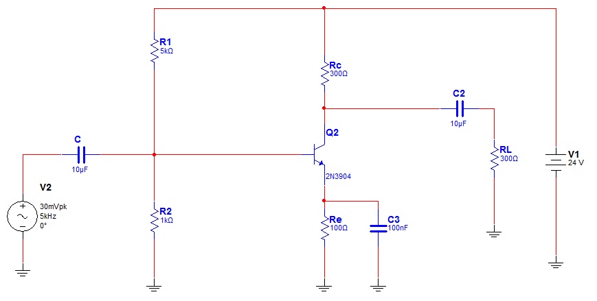
79_1292768357.jpg


Vdc=24V
Voltage to base by voltage divider=4 volts.
so 4-0.7=3.3
so Ve=3.3V.

The Ic=3.3/100=33mA
And as my knowledge,the Base current should 10 times more than Ib..
So
Ib=Ic/hfe..
Ic=33mA
Hfe=100 optimal
0.033/100=0.00033;
So 10*Ib=0.0033;
And now calculating the Voltage divide<<<
R1=6K
R2=1.2k

Now my doubt is how do u calculate the Rc..
please explain me how did that 300ohm resistor at the collector came..
please explain me thoroughly..please
 

From your requirements (without any gain) you can select Rc within reasonable limits.
Then, the gain is approximately proportional to Rc.
However, if Rc is too large, the BJT leaves the active (amplification) region. That's a typical design task that always requires a compromize.
 

^But can u calculate and show how much u would pick...

---------- Post added at 16:55 ---------- Previous post was at 16:35 ----------

i generally select Rc value assuming you that i didn't know the value of Rc, how would i calculate it?

Ve = 3.3 volts. For max collector swing, i want Vc half way between the min and the max, with 3.3v being the min, and 24 being the max. Average of those two is about 10.7 volts.
In simple words,Vc(24V)-Ve(3.3V)=20.7V
And divide it by 2..so:- 20.7/2=10V..
Added to 3.3 volts, to get 14 volts. Which means 10 volts across the resistor. R = 10/0.033 = 300 ohms


So wat do u think about my understanding...Am i right?:-?
 
Last edited:

I think this is correct.

I'm not sure what your BJT model is, but usually there is also a minimum Vce_Saturated that the BJT can have as well which would just change your minimum voltage at the collector to be something slightly higher than 3.3V

Also, just one question, usually Ib is the base current and hfe*Ib=Ic. I'm confused where that factor of 10 appeared from. The bias current calculations assumes one big thing that you might want to keep in mind in the future.
-Ic approximately = Ie since Ie = Ic+Ib. So Ie=Ic when Ib<<Ic. Basically, this means that hfe is large (100 is usually "large enough" to make Ib irrelevant)
 

Status
Not open for further replies.

Similar threads

Part and Inventory Search

Welcome to EDABoard.com

Sponsor

Back
Top