Khazan
Junior Member level 1
Please see the attached schematic. I am experimenting with a circuit for sampling an external frequency. At first, I suspected the breadboard and I replaced it with no success and then l I realized that the counters do not always count correctly.
I would like to know if anybody understands what mistake I have in my circuit which results in wrong count. It seems to me the only reason could be timing. I also experimented with timbases of 8, 16, 64, 128, 256 and 512 HZ. But it looks like that a timebase with lower frequency produces less sever errors for counting the pulses.
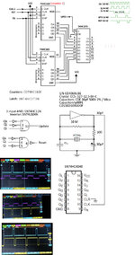
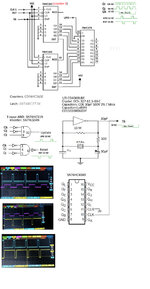
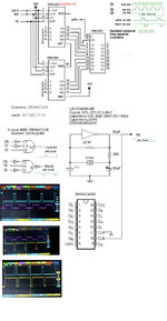
The update pulse (UPD) and reset pulse (RST) are derived from AND gates and inverters fed by the outputs Qk, Qj and Qi of a 4040 counter which divides a 32768 HZ frequency obtained from a crystal controlled timebase. All ICs are bypassed by a capacitor from their VCC to ground.
The 163 counters count during half cycle of the 32 HZ timebase or during 1/64 seconds. The output of the counters is fed to a 373 latch. If, for example, the counter counts the 1 HZ during 1/64 sec, then the output of the latch should be 1000 / 64 = 15.6 as either 15 or 16.
The problem is that the count, which I verify by an oscilloscope at the output of the latch, is not correct and the problem could be metastability which was not resolved with two D flip-flops is series.
Here are some examples:
Clock = I HZ, output of the latch is 00011111 which is double of 00001000.
Clock = 2 KHZ, output is 00111111 which corresponds to 4 KHZ.
Clock = 2.4 KHZ, output is 00100111 which corresponds to 2.96 KHZ.
Clock = 3 KHZ, output is 00101111 which corresponds to 3.008 KHZ and is acceptable.
Clock = 4 KHZ, output is 00111111 which corresponds to 4.032 KHZ .
Clock = 4.6 KHZ, output is 01001010 which corresponds to 4.736 KHZ .
Clock = 5 KHZ, output is 01001111 which corresponds to 5.056 KHZ .
Clock = 8 KHZ, output is 01111111 which corresponds to 8.128 KHZ .
Clock = 9 KHZ, output is 10001111 which corresponds to 9.344 KHZ .
Clock = 10 KHZ, output is 10011010 which corresponds to 9.856 KHZ .
I am particularly concerned with when the error at the output of latch is more than 65 HZ.
I use pulse generator of my oscilloscope for generating the input clock frequency to the 163 counters.
When I use output of Qf (1 KHZ) of the 4040 of the timebase generator as input clock formthe 163 counters, I do get the correct count at the output of the latch. This reveals the timing issue for getting the right count of an external frequency. So, how can we correctly read (sample) an external clock frequency that comes from a source other than the 4040?
The actual connection of counters and latch is as shown in the original schematics. I included the timebase generator, the gates, part numbers, and a picture of the oscilloscope. I had taken the pictures when I was testing 16 HZ timebase with similar results. I had two probes but unfortunately one of my probes is now defective so I could not show the pulses on one screen when I took the new picture with 32 HZ. I hope this can help. When I used a low pass filter of 100 KHZ all outputs of the latch went high. So I eliminated the filter from the circuit.
Could someone who is well experienced with digital frequency sampling and metastability tell me why the count is wrong specially when the count is double?
I appreciate your response and thank you.
I would like to know if anybody understands what mistake I have in my circuit which results in wrong count. It seems to me the only reason could be timing. I also experimented with timbases of 8, 16, 64, 128, 256 and 512 HZ. But it looks like that a timebase with lower frequency produces less sever errors for counting the pulses.
The update pulse (UPD) and reset pulse (RST) are derived from AND gates and inverters fed by the outputs Qk, Qj and Qi of a 4040 counter which divides a 32768 HZ frequency obtained from a crystal controlled timebase. All ICs are bypassed by a capacitor from their VCC to ground.
The 163 counters count during half cycle of the 32 HZ timebase or during 1/64 seconds. The output of the counters is fed to a 373 latch. If, for example, the counter counts the 1 HZ during 1/64 sec, then the output of the latch should be 1000 / 64 = 15.6 as either 15 or 16.
The problem is that the count, which I verify by an oscilloscope at the output of the latch, is not correct and the problem could be metastability which was not resolved with two D flip-flops is series.
Here are some examples:
Clock = I HZ, output of the latch is 00011111 which is double of 00001000.
Clock = 2 KHZ, output is 00111111 which corresponds to 4 KHZ.
Clock = 2.4 KHZ, output is 00100111 which corresponds to 2.96 KHZ.
Clock = 3 KHZ, output is 00101111 which corresponds to 3.008 KHZ and is acceptable.
Clock = 4 KHZ, output is 00111111 which corresponds to 4.032 KHZ .
Clock = 4.6 KHZ, output is 01001010 which corresponds to 4.736 KHZ .
Clock = 5 KHZ, output is 01001111 which corresponds to 5.056 KHZ .
Clock = 8 KHZ, output is 01111111 which corresponds to 8.128 KHZ .
Clock = 9 KHZ, output is 10001111 which corresponds to 9.344 KHZ .
Clock = 10 KHZ, output is 10011010 which corresponds to 9.856 KHZ .
I am particularly concerned with when the error at the output of latch is more than 65 HZ.
I use pulse generator of my oscilloscope for generating the input clock frequency to the 163 counters.
When I use output of Qf (1 KHZ) of the 4040 of the timebase generator as input clock formthe 163 counters, I do get the correct count at the output of the latch. This reveals the timing issue for getting the right count of an external frequency. So, how can we correctly read (sample) an external clock frequency that comes from a source other than the 4040?
The actual connection of counters and latch is as shown in the original schematics. I included the timebase generator, the gates, part numbers, and a picture of the oscilloscope. I had taken the pictures when I was testing 16 HZ timebase with similar results. I had two probes but unfortunately one of my probes is now defective so I could not show the pulses on one screen when I took the new picture with 32 HZ. I hope this can help. When I used a low pass filter of 100 KHZ all outputs of the latch went high. So I eliminated the filter from the circuit.
Could someone who is well experienced with digital frequency sampling and metastability tell me why the count is wrong specially when the count is double?
I appreciate your response and thank you.