Continue to Site

Welcome to EDAboard.com

Welcome to our site! EDAboard.com is an international Electronics Discussion Forum focused on EDA software, circuits, schematics, books, theory, papers, asic, pld, 8051, DSP, Network, RF, Analog Design, PCB, Service Manuals... and a whole lot more! To participate you need to register. Registration is free. Click here to register now.

differential amplifier biasing

Status
Not open for further replies.

theboss4

Junior Member level 1
Joined
Jun 2, 2008
Messages
16
Helped
0
Reputation
0
Reaction score
0
Trophy points
1,281
Activity points
1,422
Hi, thanks in advanced for your help. I'm very new to circuit designs so let me know if you further information is needed to clarify the question.

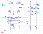
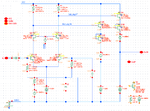
I have attached a screen capture of the circuit (differential amplifier for driving Gilbert mixer LO amplifier) in question. I'm trying to add a feature (maybe by using pull up resistor through a fET) to the design where dc volt for OutN and OutP are +/- 50mV; for example, Outn would be 2.9v and Outp would be 3.1v. Usually there's a sine wave at the input which creates square wave (with Common mode of 3.05v) at both outputs. My plan with the new feature will be to have a constant DC voltage at the outputs. Please let me know if it's possible to implement such a circuit.

Thanks!
 

Attachments

  • LO_driver_v4.png
    LO_driver_v4.png
    23 KB · Views: 75

I couldn't read anything on your negative schematic (Cadence?) so I changed it to a normal positive and increased the contrast about 5 times higher. But the schematic is covered with Chicken Pox dots and its parts are so far apart that the text is too small to be seen clearly.
 

Attachments

  • differential amp.png
    differential amp.png
    17.6 KB · Views: 84

sorry about that. here is clearer version of the schematic. let me know if you have any other question.
LO_driver_v4_r2.png
 

Again I increased the contrast of your now positive schematic. Since your outputs are emitter-followers with a diode in series then 3.05V is as high as they can go with a 5V supply.
 

Attachments

  • differential amp.png
    differential amp.png
    142.1 KB · Views: 72

Again I increased the contrast of your now positive schematic. Since your outputs are emitter-followers with a diode in series then 3.05V is as high as they can go with a 5V supply.

yes, i agree that the output might not be a good area to modify the design, since it already at the rail. However, i was thing that there might be something that i can do at the input section to change the base bias voltage so that the final dc output is pegged high (outp - 3.1V) and low (outn - 2.9V). Please let me know. thanks.
 

I am assuming that the numbers in orange are voltage but the letter "V" is not shown. R3 and R30 have no voltage drop so they have no current (their current is so low that the voltage drop is not shown).
The values of the resistors are not shown.
 

Status
Not open for further replies.

Similar threads

Part and Inventory Search

Welcome to EDABoard.com

Sponsor

Back
Top