theboss4
Junior Member level 1
Hi, thanks in advanced for your help. I'm very new to circuit designs so let me know if you further information is needed to clarify the question.
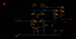
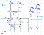
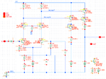
I have attached a screen capture of the circuit (differential amplifier for driving Gilbert mixer LO amplifier) in question. I'm trying to add a feature (maybe by using pull up resistor through a fET) to the design where dc volt for OutN and OutP are +/- 50mV; for example, Outn would be 2.9v and Outp would be 3.1v. Usually there's a sine wave at the input which creates square wave (with Common mode of 3.05v) at both outputs. My plan with the new feature will be to have a constant DC voltage at the outputs. Please let me know if it's possible to implement such a circuit.
Thanks!