Continue to Site

Welcome to EDAboard.com

Welcome to our site! EDAboard.com is an international Electronics Discussion Forum focused on EDA software, circuits, schematics, books, theory, papers, asic, pld, 8051, DSP, Network, RF, Analog Design, PCB, Service Manuals... and a whole lot more! To participate you need to register. Registration is free. Click here to register now.

difference between positive and negative linear regulator

Status
Not open for further replies.

learning_curve

Member level 1
Joined
Sep 10, 2010
Messages
38
Helped
3
Reputation
6
Reaction score
3
Trophy points
1,288
Activity points
1,518
Can somebody help me understand what the difference between a positive and negative voltage regulator is ?

Does it mean that the output is with respect to VDD or VSS ?
And if it is with respect to VDD is the output device a pmos?
and if it is with respect to VSS, the output device is a nmos?
 

Can somebody help me understand what the difference between a positive and negative voltage regulator is ?

Does it mean that the output is with respect to VDD or VSS ?
And if it is with respect to VDD is the output device a pmos?
and if it is with respect to VSS, the output device is a nmos?

Instead of going through a long explanation, please note:

Trying to generalize is not the way. Consider them separately and case by case.

Take the positive first and consider that whatever voltage is mentioned, it is referred to common / ground. That is the basic way to reference voltages. Otherwise, the description will explicitly say so (as in the case of internal reference voltages that could / could be not referred to ground). LM317 and MIC29152 have a difference here.

The topology used for an specific regulator does not repeat in others doing the same even if they are positive (or negative ones). Datasheets use to bring simplified schematics showing how they work.
 
thank you atferrari for your reply.
suppose there is no explicit description, looking at any schematic,
how will I know if a certain voltage is referenced to VDDA or VSSA?
 

Assuming you mean a negative supply where a positive supply is present as well...

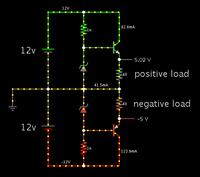
This is one of those instances where it helps when we can see the current direction through the wires. So I made a simulation showing the simplest configuration.

The link below will open the animated simulator at falstad.com/circuit, load my schematic (below), and run it on your computer. (Click Allow to load the Java applet.)

https://tinyurl.com/ahs7owl

Screenshot:


The positive regulator is an NPN with a zener diode setting the bias. In essence this is what a 7805 does.

The negative is a PNP. In essence this is what a 7905 does.
 
thank you atferrari for your reply.
suppose there is no explicit description, looking at any schematic,
how will I know if a certain voltage is referenced to VDDA or VSSA?

Please say what is VDDA and VSSA? And please also say what is their relationship with ground / common. That could help to understand the whole thing.
 

VDDA is the power supply and VSSA is ground.
But I think, I posted a wrong question. It is ambiguous.

I just wanted to understand the basics of a negative voltage regulator.
 

Status
Not open for further replies.

Part and Inventory Search

Welcome to EDABoard.com

Sponsor

Back
Top