deepsetan
Advanced Member level 4

Hi guys,
Currently, I've been working on with my design which is a MEMS oscillator that uses Silterra 0.13um technology. This is my parameter that I've calculated from the simulation (Id-Vds,Id-Vgs) and also some information from 0.13um design kit. From my simulation, I got Id=22uA. I actually obtained the Id from Id-Vgs simulation.
Vth=0.546V
Vdd=3.3V
Vds=0.5Vdd=1.65V
Vgs=1.546V
Cox=1.72m
Un=0.050542
From all of this information, how can I determine the perfect value of W/L for my design?. I knew that in order to determine the value of W/L, we can just use Id=K(Vgs-Vth)^2 (saturation formula). From the book, it says that if we use the minimum length, it will produce high speed design. Does it possible for my MEMS in real fabrication process? Can I use that minimum length for my design? Or I just can pick up any value greater than the minimum length?
- - - Updated - - -

 this is my simulation for Id-Vgs and Id-Vds
- - - Updated - - -
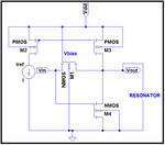
 this is my circuit that I've been working on.
Currently, I've been working on with my design which is a MEMS oscillator that uses Silterra 0.13um technology. This is my parameter that I've calculated from the simulation (Id-Vds,Id-Vgs) and also some information from 0.13um design kit. From my simulation, I got Id=22uA. I actually obtained the Id from Id-Vgs simulation.
Vth=0.546V
Vdd=3.3V
Vds=0.5Vdd=1.65V
Vgs=1.546V
Cox=1.72m
Un=0.050542
From all of this information, how can I determine the perfect value of W/L for my design?. I knew that in order to determine the value of W/L, we can just use Id=K(Vgs-Vth)^2 (saturation formula). From the book, it says that if we use the minimum length, it will produce high speed design. Does it possible for my MEMS in real fabrication process? Can I use that minimum length for my design? Or I just can pick up any value greater than the minimum length?
- - - Updated - - -

 this is my simulation for Id-Vgs and Id-Vds
- - - Updated - - -
 this is my circuit that I've been working on.
