Continue to Site

Welcome to EDAboard.com

Welcome to our site! EDAboard.com is an international Electronics Discussion Forum focused on EDA software, circuits, schematics, books, theory, papers, asic, pld, 8051, DSP, Network, RF, Analog Design, PCB, Service Manuals... and a whole lot more! To participate you need to register. Registration is free. Click here to register now.

Delay Line Time To digital Converter

Lizwi

Newbie
Joined
Mar 3, 2024
Messages
2
Helped
0
Reputation
0
Reaction score
0
Trophy points
1
Activity points
15
Hi

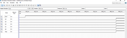
I am simulating a time to digital converter using Verilog in Quartus. It consists of both coarse and fine measurement. I have already simulated counter using structural modelling.
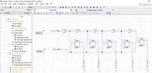
Please help me with a code to simulate a tapped delay line like in the picture. The buffers must have a delay. Please please help me.
Tapped-delay-line-TDC (1).png
 
What do you mean with "simulating in Quartus"? Quartus itself is no simulator (unless you are using pre V13 version with builtin simulation capabilties). It makes use of Modelsim respectively Questasim if you are starting simulation flow out of Quartus. Are you asking about timing simulation of Quartus generated netlist?

Design-wise, you need to prevent the synthesis tool from optimizing the buffers away, e.g. by "keep" synthesis attributes. What's the intended time resolution of your TDC design?

In practice, it's difficult up to impossible to achieve uniform time delay over more than a few (e.g. 8) stages because routing delay between LAB adds to basic LE delay.
 
Maybe few nanoseconds bout 10ns resolution.

I did model the tapped delay line using Schematics, I expected the waveform to show that each flip flop output logic one at different times because I added buffers to delay each input from the buffer to the flip flop, but it seems all flip flop are outputting logic one at the same time. No delays.
 

Attachments

  • Capture.PNG
    Capture.PNG
    29.4 KB · Views: 48
  • Capture2.PNG
    Capture2.PNG
    76.7 KB · Views: 41
As said, you need synthesis attributes to keep the buffers. They can be also set in schematic entry, but I'm not aware of the syntax.
--- Updated ---

Looked at the timing diagram, it doesn't make much sense for me. Expected delay per buffer is only a few 100 ps.
 
Last edited:

LaTeX Commands Quick-Menu:

Part and Inventory Search

Welcome to EDABoard.com

Sponsor

Back
Top