Continue to Site

Welcome to EDAboard.com

Welcome to our site! EDAboard.com is an international Electronics Discussion Forum focused on EDA software, circuits, schematics, books, theory, papers, asic, pld, 8051, DSP, Network, RF, Analog Design, PCB, Service Manuals... and a whole lot more! To participate you need to register. Registration is free. Click here to register now.

delay analog signal (continuous )

Status
Not open for further replies.
Using inductors and capacitors as a lumped approximation to a transmission line is a well known technique for delaying signals (it was one of the example circuits I showed earlier).

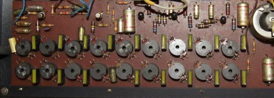
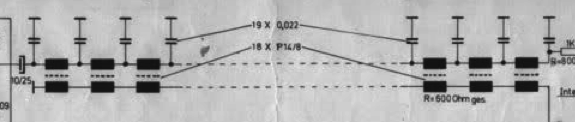
Yes, you posted the 'Delay amp.pdf' configuration. It is made from several coils strung in series, with capacitors to ground in between.

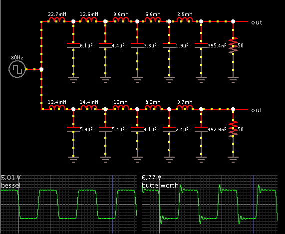
The arrangement is similar to the multi-pole Butterworth filter (low pass) which I find among the circuits that come with Falstad's simulator.

I strung together several stages and made a simulation.


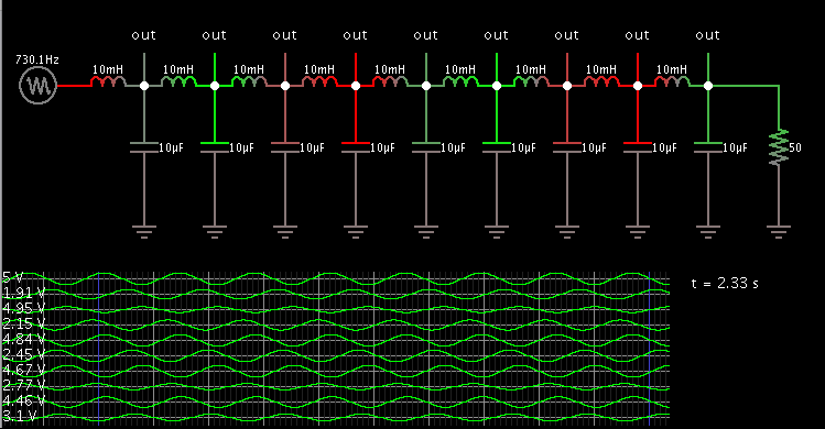
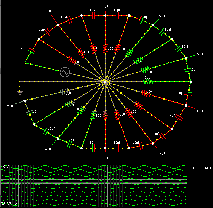
The red coloring moves from left to right continuously.

Resonant action is obvious in the animation. It causes some stages to 'bend' its sine wave so it is a little ahead or behind where it ought to be.

The volt levels do not decrease so quickly. With resonant action going on, there may even be some stages swinging to a higher level than the original signal.

It dawns on me that this is the concept that a transmission line takes advantage of, in order to minimize signal loss.
 

The LC ladder acts as a transmission line equivalent at frequencies considerably below the low-pass cut-off frequency respectively LC resonance.

You'll notice, that low-pass filters with smooth transmission characterictic, e.g. butterworth type have stepped inductance and capacitance values, reducing the resonance elevation. A LC delay line will use equal LC values for maximum delay and thus can't avoid resonance effects. This becomes a problem when delaying wide-band signals, e.g square waves.

The original poster didn't mention any delay/signal frequency numbers, in so far it's still unclear if LC delay lines can be a solution.

P.S.: I remember an electronic Leslie effect (a simulation of the frequency modulation by rotating speakers popular with Hammond organs) made by a German company in the pre-DSP (and pre CCD-IC) age. It used a LC delay line with variable inductance, controlled by a superimposed DC current.

P.P.S.: The name of the effect is Schaller Rotor Sound. You'll find some schematics and photos on the internet.
 
Last edited:

The LC ladder acts as a transmission line equivalent at frequencies considerably below the low-pass cut-off frequency respectively LC resonance.

You'll notice, that low-pass filters with smooth transmission characterictic, e.g. butterworth type have stepped inductance and capacitance values, reducing the resonance elevation. A LC delay line will use equal LC values for maximum delay and thus can't avoid resonance effects. This becomes a problem when delaying wide-band signals, e.g square waves.

The butterworth type is included in Falstad's simulator, and a Bessel filter, with a side-by-side comparison:


Comparing component values, I see the Bessel type encompassses a wider range of values, yet that slight difference seems to do away with ringing.

P.S.: I remember an electronic Leslie effect (a simulation of the frequency modulation by rotating speakers popular with Hammond organs) made by a German company in the pre-DSP (and pre CCD-IC) age. It used a LC delay line with variable inductance, controlled by a superimposed DC current.

P.P.S.: The name of the effect is Schaller Rotor Sound. You'll find some schematics and photos on the internet.

Yes, the Leslie had two speakers spinning slowly or quickly, under control of a pedal. Doppler effect played a part in the unique sound.

Someone posted photos of the circuit board. Here it shows 18 coils and 18 capacitors:


Portion of the schematic:


Screenshot of my simulation using 18 capacitors in series.

When coils are used this way, they create a delay. However using capacitors advances the phase.

Here the values and frequency are chosen to advance the signal 2 cycles. The scope traces tell what is happening. (At a freq of 150 Hz, the advance is .013 sec.)

It's just math in motion, but still there is a paradox going here which I have trouble getting my mind around.


Because the initial arrangement had so many plain ground wires, I connected them all to a center hub and wound the remainder into a wheel shape.

The red and green spoke patterns rotate around the hub, counter-clockwise.

The scope traces travel across the screen just like waves on the ocean.

The yellow dots travel up and down the wires like beads of dew on a spider's web.

Never have I seen anything like it before.

Clickable link which will load my simulation and run it on anyone's computer. (Click Allow to load the Java applet. Maximize the window size.)

https://tinyurl.com/byjr6cn
 

Status
Not open for further replies.

Similar threads

Part and Inventory Search

Welcome to EDABoard.com

Sponsor

Back
Top